Remote I/O R80 Series
Tình trạng: In stock
Contact: 0989649965
R80 Remote I/O R80 Series R80 SERIES GENERAL SPECIFICATIONS
Số lượt xem: 1517
Detail
·Some details are not shown. Please refer to specification sheets for all information.
R80
Remote I/O R80 Series
R80 SERIES GENERAL SPECIFICATIONS
Functions & Features
• Remote I/O modules which interchange analog or digital I/O signals with the fieldbus
• Space-saving
Typical Applications
• Remote I/O for DCS and PLC
• Personal computer I/O
ORDERING INFORMATION
Refer to the specifications of the respective modules for details.
POWER/NETWORK MODULE: R80[1]-R
Refer to the specifications for the respective models.
[1] MODULE TYPE
NECT1: EtherCAT
POWER INPUT
DC power
R: 24 V DC
(Operational voltage range: ±10 %; ripple 10 %p-p max.)
I/O MODULE: R80[1]
Refer to the specifications for the respective models.
[1] MODULE TYPE
• Discrete Input
DAT8A: Discrete input (NPN), 8 points (Tension clamp terminal block)
• Discrete Output
DCT8A: Transistor output (NPN), 8 points (Tension clamp terminal block)
Since internal power supply source and internal
communication bus are performed through the connector of
each module, installation base is unnecessary.
FUNCTIONS & FEATURES
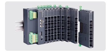
The R80 Series Remote I/O is composed of power/network modules and I/O modules.
■ I/O MODULE
Performs data conversion of field inputs; Data conversion of data received through the internal bus into outputs.
■ POWER/NETWORK MODULE
The power/network module supplies the I/O modules with required internal electrical power source.
The power/network module changes the receiving data from internal bus into output signal and vice versa, acts as a gateway between transmission line and internal bus.
■ HOT INSERTION/REMOVAL OF I/O MODULES
Since internal power supply and internal bus are performed through the connector of each module, it cannot be replaced with the power on.
■ DIELECTRIC STRENGTH
As dielectric strength differs depending on each module, refer to each specification sheet.
RELATED PRODUCTS
• PC configurator software (model: R80CFG)
Downloadable at M-System’s web site.
For connecting to PC, use commercially available Mini-B type USB cable. (provided by user)
GENERAL SPECIFICATIONS
Power input:
•R80NECT1-R
24 V DC ±10 %; ripple 10 %p-p max.
Power consumption
•DC: Approx. 12 W
24 V DC (@ output current 1.6 A)
Internal power
•DC: 5 V DC
•Operational current: 1.6 A
Excitation supply output
•DC: 24 V DC ±10 %
•Operational current: 10 A
(Power output current consumption must be under rated current)
Operating temperature: -10 to +55°C (14 to 131°F)
Operating humidity: 30 to 90 %RH (non-condensing)
Atmosphere: No corrosive gas or heavy dust
Mounting: DIN rail (35 mm wide)
Connection
•Power/network module
·Power supply, exc. supply:
Tension clamp terminal block (Front twin connection)
Applicable wire size: 0.2 to 2.5 mm2, stripped length 10 mm
·EtherCAT: RJ-45 connector
•I/O module:
Tension clamp terminal block
Applicable wire size: 0.2 to 1.5 mm2, stripped length 10 mm
Housing material: Flame-resistant resin (black)
Max. number of I/O modules: 16 (module address: 0 to 15)
Internal communication bus: Transmission cycle approx. 65 μsec. + 65 μsec. x No. of Modules
■ Weight
R80NECT1: 210 g (0.46 lb)
R80DAT8A: 80 g (0.18 lb)
R80DCT8A: 80 g (0.18 lb)
Protective cover: 15 g (0.03 lb)
CURRENT CONSUMPTION
The I/O modules operate by the DC voltage (5 V DC) supplied from the power/network module. Arrange these modules in order that the total current consumed by these modules can be within the supply current capacity. If the current consumption exceeds the limit, change the combination of I/O modules or reduce the no. of modules mounted. Even if total consumption current of the I/O modules is less than the supply current capacity, the total install number of the modules is max. 16.
■ Max. current consumption
R80DAT8A: 100 mA
R80DCT8A: 120 mA
USING EXCITATION SUPPLY
Some I/O modules use excitation supply, on the other hand some I/O modules do not. When excitation supply is cut off during power supply is on, operation is as the table shown below.
BASIC CONFIGURATION
The number of I/O modules that can be mounted changes depending on the power/network module. Refer to the specifications of each power/network module for details.
Althoug the module address can be arbitrarily set regardless of its mounting position, to avoid overlapped and unused addresses, set them consecutively starting at 0.
Only for rightmost module, set termination resistor to enable. Protective cover is included in the package of power/network module.
MOUNTING REQUIREMENTS unit: mm (inch)
SYSTEM CONFIGURATION EXAMPLES
M-System Co., Ltd.
Products
-
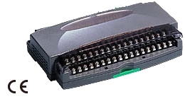
R1MS-GH3 THERMOCOUPLE & DC INPUT MODULE
R1MS-GH3 Remote I/O R1M Series THERMOCOUPLE & DC INPUT MODULE (8 points, isolated)
-
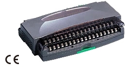
R1M-P4/MSR PC RECORDER
-
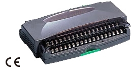
R1M-P4 Remote I/O R1M Series
R1M-P4 Remote I/O R1M Series CONTACT I/O MODULE (4 totalized counter inputs, 8 contact inputs and outputs)
-
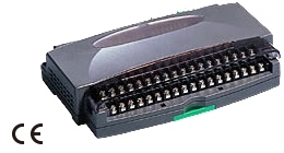
R1M-J3/MSR PC Recorders R1M Series
R1M-J3/MSR PC Recorders R1M Series PC RECORDER (RTD or potentiometer input, 8 points)
-
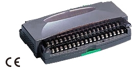
R1M-J3 Remote I/O R1M Series
R1M-J3 Remote I/O R1M Series RTD & POTENTIOMETER INPUT MODULE (8 points)
-
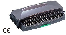
R1M-GH/MSR PC Recorders R1M Series
R1M-GH/MSR PC Recorders R1M Series PC RECORDER (thermocouple or DC input, 16 points)
-
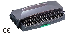
R1MS-GH3/MSR PC Recorders R1M Series
R1MS-GH3/MSR PC Recorders R1M Series PC RECORDER
-
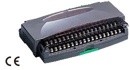
R1D-GH2 THERMOCOUPLE & DC INPUT MODULE
R1D-GH2 Remote I/O R1X Series THERMOCOUPLE & DC INPUT MODULE (16 points; DeviceNet)
-
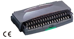
R1C-GH THERMOCOUPLE & DC INPUT MODULE
R1C-GH Remote I/O R1X Series THERMOCOUPLE & DC INPUT MODULE (16 points; CC-Link Ver.1.10/Ver.2.00)
PRODUCTS LIST
- Signal Conditioners
- 2-wire Signal Conditioners
- Power Transducers
- Indicators
- Tower Lights
- Limit Alarms
- Gateway, Remote IO
- Paperless Recording System
- PC Recorder
- Web Data Loggers
- PID Control Components
- BA&Energy Monitoring Components
- Temperature Controllers
- Electric Actuators
- Lightning Surge Protectors
STATISTIC
Visitor: 1064525Online: 19

 Xem ảnh gốc


