R1MS-GH3/MSR PC Recorders R1M Series
Tình trạng: In stock
Contact: 0989649965
R1MS-GH3/MSR PC Recorders R1M Series PC RECORDER
Số lượt xem: 2032
Detail
·Some details are not shown. Please refer to specification sheets for all information.
R1MS-GH3/MSR
PC Recorders R1M Series
PC RECORDER
(thermocouple or DC input, 8 points; isolated)
Functions & Features
• Industrial recorder on PC
• 8-point thermocouple or DC inputs
• Complete channel-to-channel isolation
• Trigger input and alarm contact output
• Filtering protection against 50/60 Hz noise
• Modbus RS-485 and RS-232-C interface
• Easy system expansion via Modbus RTU
• Recorded data exportable to spreadsheet applications
MODEL: R1MS-GH3T-[1][2]
ORDERING INFORMATION
• Code number: R1MS-GH3T-[1][2]
Specify a code from below for each [1] and [2].
(e.g. R1MS-GH3T-M2/MSR/Q)
• Specify the specification for option code /Q
(e.g. /C01)
FIELD TERMINAL TYPE
T: M3 screw terminals
[1] POWER INPUT
AC Power
M2: 100 – 240 V AC (Operational voltage range 85 – 264 V,
47 – 66 Hz)
DC Power
R: 24 V DC
(Operational voltage range 24 V ±10 %, ripple 10 %p-p max.)
[2] OPTIONS (multiple selections)
PC Recorder Software Package (must be specified)
/MSR: With
Other Options
blank: none
/Q: Option other than the above (specify the specification)
SPECIFICATIONS OF OPTION: Q
COATING (For the detail, refer to M-System's web site.)
/C01: Silicone coating
/C02: Polyurethane coating
/C03: Rubber coating
RELATED PRODUCTS
• Resistor module (model: REM3-250)
PACKAGE INCLUDES...
• PC Recorder Software CD
• 9-pin D-sub connector, straight type (1 m or 3.3 ft)
GENERAL SPECIFICATIONS
Connection
Power input, transmission: Euro type connector terminal
(Applicable wire size: 0.2 – 2.5 mm2 (AWG24 – 12), stripped
length 7 mm)
RS-232-C: 9-pin D-sub connector (male)
(Lock screw No. 4-40 UNC)
I/O: M3 screw terminals (torque: 0.6N·m)
PC Configurator: Miniature jack, RS-232-C level
Screw terminal: Nickel-plated steel
Housing material: Flame-resistant resin (gray)
Isolation: Input 1 to input 2 to input 3 to input 4 to input 5 to input 6 to input 7 to input 8 to trigger input to alarm output to RS-232-C or RS-485 or configurator jack to power to FG
Burnout: Upscale, downscale or no burnout selectable with the operating mode setting rotary switch (default: No). Set to ‘No Burnout’ when other devices are connected in parallel to the R1MS.
Operating mode setting: Rotary switch; burnout type and line noise frequency setting
Line noise filtering: Specifying line frequency to 50 Hz or 60 Hz in order to increase normal mode noise rejection ratio. (default: 50/60 Hz for use with both frequencies)
Node address setting: Rotary switch; 1 – F (15 nodes)
RUN indicator LED: Green light blinks in normal conditions.
COMMUNICATION
Baud rate: 38.4 kbps
Communication: Half-duplex, asynchronous, no procedure
Protocol: Modbus RTU
■ RS-232-C
Standard: Conforms to RS-232-C, EIA
Transmission distance: 10 meters max.
■ RS-485
Standard: Conforms to TIA/EIA-485-A
Transmission distance: 500 meters max.
Transmission media: Shielded twisted-pair cable (CPEV-S 0.9 dia.)
INPUT SPECIFICATIONS
Input: Thermocouple or DC input within ±10 V, 8 points
• Input resistance
Thermocouple: ≥ 1 MΩ when powered;
≥ 200 kΩ when not powered
DC: ≥ 800 kΩ when powered;
≥ 700 kΩ when not powered
Thermocouple types: PR, K, E, J, T, B, R, S, C, N, U, L, P
Sampling rate: 50 millisec./8 points
• Trigger input: Dry contact; ON detected at ≤ 1.5 V
Sensing: Approx. 3 V DC @ 0.8 mA
• Burnout detecting: ≤ 45 nA for upscale or downscale;
≤ 5 nA with no burnout (when measuring 0°C)
Burnout response: ≤ 10 seconds
OUTPUT SPECIFICATIONS
■ Alarm Output: Photo MOSFET relay (no polarity);
≤ 50 Ω at ON, ≥ 1 MΩ at OFF; OFF when not powered
Peak load voltage: 50 V max.
Continuous load current: 50 mA max.
Peak load current: 300 mA max. (≤ 0.1 sec.)
INSTALLATION
Power consumption
•AC: Approx. 9 VA
•DC: Approx. 3.5 W
Operating temperature: -5 to +60°C (23 to 140°F)
Operating humidity: 30 to 90 %RH (non-condensing)
Mounting: Surface or DIN rail
Weight: 450 g (0.99 lb)
PERFORMANCE (% of measuring range)
Accuracy
DC input: ±0.05 % (±10 mV)
Thermocouple input: See the table below.
Cold junction compensation error: (°C)
≤ ±(1.0 + [Ambient Temp. – 20] × 0.04) in stable ambient temperature (e.g. ±1.4°C at 10°C and 30°C)
Sudden ambient temperature change affects the cold junction compensation. Be sure to place the R1MS in stable ambient.
Temp. coefficient: ≤ (Accuracy / 4) / °C
(e.g. DC: ±0.0125 %/°C or ±2.5 mV/°C,
TC: ±12.5 μV/°C, ±0.2°C/°C with type E)
Response time: Approx. 0.55 sec. (0 – 90 %)
Insulation resistance: ≥ 100 MΩ with 500 V DC
Dielectric strength: 1500 V AC @ 1 minute
(input 1 to input 2 to input 3 to input 4 to input 5 to input 6 to input 7 to input 8 to trigger input to alarm output to RS-232-C or RS-485 or configurator jack)
2000 V AC @ 1 minute (input or alarm output or RS-232-C or RS-485 or configurator jack to power to FG)
Normal mode noise rejection: ≥ 85 dB (50/60 Hz) with the filtering set to a specific frequency; ≥ 35 dB with 50/60 Hz setting
Common mode noise rejection: ≥ 120 dB (50/60 Hz)
PC RECORDER SOFTWARE
PC Recorder Software Package (model: MSRPAC-2010) is included with purchases of this model.
Refer to the MSRPAC-2010 data sheet for the contents of the package and the requirements for the PC to be prepared by the user.
EXTERNAL VIEW
MODBUS WIRING CONNECTION
CONNECTION DIAGRAM
EXTERNAL DIMENSIONS & TERMINAL ASSIGNMENTS unit: mm (inch)
SYSTEM CONFIGURATION EXAMPLES
M-System Co., Ltd.
Products
-
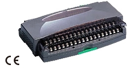
R1M-P4/MSR PC RECORDER
-
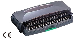
R1M-P4 Remote I/O R1M Series
R1M-P4 Remote I/O R1M Series CONTACT I/O MODULE (4 totalized counter inputs, 8 contact inputs and outputs)
-
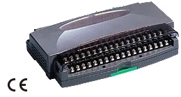
R1M-J3/MSR PC Recorders R1M Series
R1M-J3/MSR PC Recorders R1M Series PC RECORDER (RTD or potentiometer input, 8 points)
-
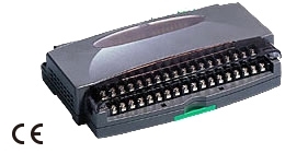
R1M-J3 Remote I/O R1M Series
R1M-J3 Remote I/O R1M Series RTD & POTENTIOMETER INPUT MODULE (8 points)
-
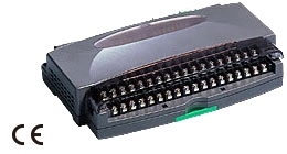
R1M-GH/MSR PC Recorders R1M Series
R1M-GH/MSR PC Recorders R1M Series PC RECORDER (thermocouple or DC input, 16 points)
-
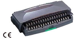
R1MS-GH3 THERMOCOUPLE & DC INPUT MODULE
R1MS-GH3 Remote I/O R1M Series THERMOCOUPLE & DC INPUT MODULE (8 points, isolated)
-
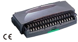
R1C-GH THERMOCOUPLE & DC INPUT MODULE
R1C-GH Remote I/O R1X Series THERMOCOUPLE & DC INPUT MODULE (16 points; CC-Link Ver.1.10/Ver.2.00)
-
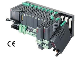
R5-YV DC VOLTAGE OUTPUT MODULE
R5-YV Remote I/O R5 Series DC VOLTAGE OUTPUT MODULE
-
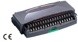
R1D-GH2 THERMOCOUPLE & DC INPUT MODULE
R1D-GH2 Remote I/O R1X Series THERMOCOUPLE & DC INPUT MODULE (16 points; DeviceNet)
PRODUCTS LIST
- Signal Conditioners
- 2-wire Signal Conditioners
- Power Transducers
- Indicators
- Tower Lights
- Limit Alarms
- Gateway, Remote IO
- Paperless Recording System
- PC Recorder
- Web Data Loggers
- PID Control Components
- BA&Energy Monitoring Components
- Temperature Controllers
- Electric Actuators
- Lightning Surge Protectors
STATISTIC
Visitor: 1050556Online: 19

 Xem ảnh gốc


