
")
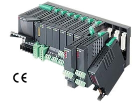
R1M-P4 Remote I/O R1M Series


Tình trạng: In stock
Contact: 0989649965
R1M-P4 Remote I/O R1M Series CONTACT I/O MODULE (4 totalized counter inputs, 8 contact inputs and outputs)
Số lượt xem: 1259
Detail
·Some details are not shown. Please refer to specification sheets for all information.
R1M-P4
Remote I/O R1M Series
CONTACT I/O MODULE
(4 totalized counter inputs, 8 contact inputs and outputs)
Functions & Features
• Totalized counter inputs
• Counts stored in E2PROM
• Easy system expansion via Modbus RTU
MODEL: R1M-P4T-[1][2]
ORDERING INFORMATION
• Code number: R1M-P4T-[1][2]
Specify a code from below for each [1] and [2].
(e.g. R1M-P4T-M2/Q)
• Specify the specification for option code /Q
(e.g. /C01)
FIELD TERMINAL TYPE
T: M3 screw terminals
[1] POWER INPUT
AC Power
M2: 100 – 240 V AC (Operational voltage range 85 – 264 V,
47 – 66 Hz)
DC Power
R: 24 V DC
(Operational voltage range 24 V ±10 %, ripple 10 %p-p max.)
[2] OPTIONS
blank: none
/Q: With options (specify the specification)
SPECIFICATIONS OF OPTION: Q
COATING (For the detail, refer to M-System's web site.)
/C01: Silicone coating
/C02: Polyurethane coating
/C03: Rubber coating
RELATED PRODUCTS
• R1X configurator software (model: R1CON)
Downloadable at M-System’s web site.
A dedicated cable is required to connect the module to the PC. Please refer to the internet software download site or the users manual for the PC configurator for applicable cable types.
GENERAL SPECIFICATIONS
Connection
Power input, transmission: Euro type connector terminal
(Applicable wire size AWG24-12 (0.2 – 2.5 mm2), stripped
length 7 mm)
RS-232-C: 9-pin D-sub connector (male)
(Lock screw No. 4-40 UNC)
I/O: M3 screw terminals (torque: 0.6N·m)
Screw terminal: Nickel-plated steel
Housing material: Flame-resistant resin (gray)
Channel selector for the digital display: Rotary DIP switch;
1 thr. 8: ch.1 thr. ch.8 contact input
A thr. D: ch.A thr. ch.D totalized counter input
0, 9, E, F: no display
Isolation: RS-232-C or RS-485 to I/O to power
Node address setting: Rotary switch; 1 – F (15 nodes)
RUN indicator LED: Green light blinks in normal conditions.
Count memory at power loss: Count value is saved in the the non-volatile memory (E2PROM) when the power supply is lost.
Number of rewritable times: 105 times
Data storing characteristics: 10 years at 20°C
■ Indicators
Digital display: 6-digit red LED; 4.6 mm high; Shows either totalized (lower 6 digits only) or momentary value; selectable with internal DIP switch
COMMUNICATION
Baud rate: 38.4 kbps
Communication: Half-duplex, asynchronous, no procedure
Protocol: Modbus RTU
Refer to Modbus Protocol Reference Guide (EM-5650) for supported functions.
■ RS-232-C
Standard: Conforms to RS-232-C, EIA
Transmission distance: 10 meters max.
■ RS-485
Standard: Conforms to TIA/EIA-485-A
Transmission distance: 500 meters max.
Transmission media: Shielded twisted-pair cable (CPEV-S 0.9 dia.)
INPUT SPECIFICATIONS
■ Totalized Counter Input (high speed): Dry contact, 4 points
Commons: All negatives
Max. input frequency: 10 kHz
Minimum pulse width: 50 μsec.
Max. counter value: 999 999 999 (reset to zero at overflow)
Sensing: Approx. 5 V DC (pull-up resistance 22 kΩ); ≤ 0.8 V at Lo; ≥ 4 V at Hi
Caution: The totalized counter itself can accept frequencies as high as 10 kHz. In order to eliminate unwanted input by chattering, be careful to choose an input device to be free of the problem (e.g. mercury relay).
■ Contact Input: Dry contact, 8 points
Commons: All negatives
Sensing: Approx. 5 V DC (pull-up resistance 22 kΩ); ≤ 0.8 V at Lo; ≥ 4 V at Hi
Sampling rate: 50 msec.
Totalizing counter function
Number of input channels: 8
Max. input frequency: 100 Hz
Minimum pulse width: 5 msec.
Max. counter value: 999 999 999 (reset to zero at overflow)
■ Counter Reset Input: Dry contact, 1 point
Commons: All negatives
Sensing: Approx. 5 V DC (pull-up resistance 22 kΩ); ≤ 0.8 V at Lo; ≥ 4 V at Hi
Sampling rate: 50 msec.
Logic: Enable at pulse edge sinking
OUTPUT SPECIFICATIONS
■ Contact Output: Open collector, 8 points
Commons: All negatives
Rating: 24 V DC @ 50 mA (resistive load)
Saturation voltage: 1.6 V DC
For use with inductive loads, external protection of contact and noise quenching is recommended.
Sampling rate: 50 msec.
INSTALLATION
Power consumption
•AC: Approx. 10 VA
•DC: Approx. 7 W
Operating temperature: -5 to +60°C (23 to 140°F)
Operating humidity: 30 to 90 %RH (non-condensing)
Mounting: Surface or DIN rail
Weight: 400 g (0.88 lb)
PERFORMANCE
Multi-transmission time: 5 msec.
Insulation resistance: ≥ 100 MΩ with 500 V DC
Dielectric strength: 2000 V AC @ 1 minute (RS-232-C or RS-485 to I/O to power to ground)
EXTERNAL VIEW
MODBUS WIRING CONNECTION
CONNECTION DIAGRAM
MODBUS COMMUNICATION
EXTERNAL DIMENSIONS & TERMINAL ASSIGNMENTS unit: mm (inch)
SYSTEM CONFIGURATION EXAMPLES
M-System Co., Ltd.
Products
-

R1MS-GH3 THERMOCOUPLE & DC INPUT MODULE
R1MS-GH3 Remote I/O R1M Series THERMOCOUPLE & DC INPUT MODULE (8 points, isolated)
-

R1M-P4/MSR PC RECORDER
-

R1M-J3/MSR PC Recorders R1M Series
R1M-J3/MSR PC Recorders R1M Series PC RECORDER (RTD or potentiometer input, 8 points)
-

R1M-J3 Remote I/O R1M Series
R1M-J3 Remote I/O R1M Series RTD & POTENTIOMETER INPUT MODULE (8 points)
-

R1M-GH/MSR PC Recorders R1M Series
R1M-GH/MSR PC Recorders R1M Series PC RECORDER (thermocouple or DC input, 16 points)
-

R1MS-GH3/MSR PC Recorders R1M Series
R1MS-GH3/MSR PC Recorders R1M Series PC RECORDER
-

R1C-GH THERMOCOUPLE & DC INPUT MODULE
R1C-GH Remote I/O R1X Series THERMOCOUPLE & DC INPUT MODULE (16 points; CC-Link Ver.1.10/Ver.2.00)
-
R5-YV DC VOLTAGE OUTPUT MODULE
R5-YV Remote I/O R5 Series DC VOLTAGE OUTPUT MODULE
-

R1D-GH2 THERMOCOUPLE & DC INPUT MODULE
R1D-GH2 Remote I/O R1X Series THERMOCOUPLE & DC INPUT MODULE (16 points; DeviceNet)
PRODUCTS LIST
- Signal Conditioners
- 2-wire Signal Conditioners
- Power Transducers
- Indicators
- Tower Lights
- Limit Alarms
- Gateway, Remote IO
- Paperless Recording System
- PC Recorder
- Web Data Loggers
- PID Control Components
- BA&Energy Monitoring Components
- Temperature Controllers
- Electric Actuators
- Lightning Surge Protectors
News Product
 IT40SW5F/6F, IT50SW5F/6F, IT60SW5F/6F Series")


STATISTIC
Visitor: 1060996Online: 17

