R8-TC2 TEMPERATURE CONTROL MODULE
Tình trạng: In stock
Contact: 0989649965
R8-TC2 Remote I/O R8 Series TEMPERATURE CONTROL MODULE
Số lượt xem: 1412
Detail
·Some details are not shown. Please refer to specification sheets for all information.
R8-TC2
Remote I/O R8 Series
TEMPERATURE CONTROL MODULE
Functions & Features
• Two PID controllers
• Universal input x 2 points, control output x 2 points, clamp-on current sensor input x 2 points
• 2 universal inputs configurable to T/C, RTD, DC current or voltage independently
• Clamp-on current sensor input enables to detect heater wire break or over current
• Auto tuning function
• Configurable with PC configurator (model: R8CFG)
• Mixed installation with other I/O modules
MODEL: R8-TC2[1][2]
ORDERING INFORMATION
• Code number: R8-TC2[1][2]
Specify a code from below for each [1] and [2].
(e.g. R8-TC2A/Q)
• Specify the specification for option code /Q
(e.g. /C01)
CONTROL LOOP
2: 2 loops
[1] CONTROL OUTPUT
A: 0 – 20 mA DC (Load resistance 450 Ω max.) 2 points
V: 0 – 10 V DC (Load resistance 2 kΩ max.) 2 points
P: 12 V voltage pulse (Load resistance 600 Ω max.) 2 points
[2] OPTIONS
blank: none
/Q: With options (specify the specification)
SPECIFICATIONS OF OPTION: Q
COATING (For the detail, refer to M-System's web site.)
/C01: Silicone coating
/C02: Polyurethane coating
RELATED PRODUCTS
• PC configurator software (model: R8CFG)
A dedicated cable is required to connect the module to the PC. Please refer to the users manual for the PC configurator for applicable cable types.
• Clamp-on current sensor (model: CLSE)
(Used for detecting the heater wire break)
Note: When using with Power/Network module (model: R8-NECT1), firmware version Ver1.30 or later is supported.
GENERAL SPECIFICATIONS
Connection
•I/O: 4-pin e-CON connector
Unit side connector XN2D-1474-S002 (Omron)
Recommended cable side connector XN2A-1470 (Omron)
Applicable wire size: 0.08 - 0.5 mm2 (AWG28 - 20)
Outer sheath diameter: max. 1.5 dia
(The cable connector is not included in the package.
Refer to the specifications of the product.)
•Excitation supply, internal bus:
Connected to internal bus connector
•Internal power: Supplied from internal bus connector
Isolation: Pv1 to Pv2 to Mv1 to Mv2 to exc.supply to CT1 or CT2 or internal bus or internal power
CT Input waveform
RMS sensing: Up to 15 % of 3rd harmonic content
Input Selection: Selectable with the side DIP SW
Cold Junction Compensation: CJC sensor incorporated
Module address: With DIP switch
Terminating resistor: Built-in (DIP Switch, default: disable)
Indicator LEDs: Bi-color (red/green) LED;
Other indicator LEDs: Green LED
Refer to the instruction manual.
Control mode: Standard PID, heating and cooling control PID
・Proportional band (P): 0.1 to 3200.0 (temperature unit)
・Integral time (I): 0 to 3999 sec.
・Derivative time (D): 0.0 to 999.9 sec.
Auto-tuning: Limit cycle method
Sampling cycle: 100 msec.
Control cycle: 1.0 to 99.9 sec.
(100 msec. fixed for Mv output 0 - 20 mA DC
and 0 - 10 V DC)
Mv output range: -5 - +105 % for output scale
Parameters: Stored in non-volatile memory; write/erase cycle endurance: less than 1 000 000
Parameter setting: With PC configurator software (model: R8CFG)
• Input
• Burnout
• CT input
• Auto-tuning
Refer to the instruction manual for detail.
INPUT SPECIFICATIONS
■ Universal input 1, 2 (Pv1, Pv2)
For input type and range configuration, refer to the instruction manual.
・DC Current:
Input range: 0 - 20 mA DC
Input resistance: 49.9 Ω resistor incorporated
• DC voltage input
Input resistance: ≥ 10 kΩ (-1000 to +1000 mV DC)
Input resistance: ≥ 1 MΩ (-10 to +10 V DC)
• Thermocouple
Input resistance: ≥ 10 kΩ
Input range: Refer to the table 1
Burnout sensing: ≤ 4 μA
Conformance range: Refer to the table 1
• RTD (2-wire or 3-wire)
Excitation: ≤ 0.33 mA
Input range: Refer to the table 1
Allowable leadwire resistance: 20 Ω per wire
• Resistor (2-wire or 3-wire)
Excitation: ≤ 0.33 mA
Input range: 0 - 4000 Ω
Allowable leadwire resistance: 20 Ω per wire
• Potentiometer
Excitation: ≤ 0.33 mA
Input range: Refer to the table 1
Allowable leadwire resistance: 20 Ω per wire
■ Clamp-on current sensor (CT1, CT2)
(Sensor model No.: AC input)
CLSE-R5: 0 – 5 A
CLSE-05: 0 – 50 A
CLSE-10: 0 – 100 A
CLSE-20: 0 – 200 A
CLSE-40: 0 – 400 A
CLSE-60: 0 – 600 A
Frequency: 50 / 60 Hz (45 - 65 Hz)
Operational range: 0 – 120 % of rating
Overload capacity:
CLSE-R5: 10 A continuous
CLSE-05: 60 A continuous
CLSE-10: 120 A continuous
CLSE-20: 240 A continuous
CLSE-40: 480 A continuous
CLSE-60: 720 A continuous
Be sure that the input voltage is of 480 V or less.
OUTPUT SPECIFICATIONS
■ Control Output (Mv1, Mv2)
Specify the type of output with the code number.
• DC Current: 0 – 20 mA DC
Operational range: 0 – 23 mA DC
Load resistance: ≤ 450 Ω
• DC Voltage: 0 – 10 V DC
Operational range: 0 - 11.5 V DC
Load resistance: ≥ 2 kΩ
■ Voltage Pulse
Maximum frequency: 1 Hz
Minimum pulse width: 1 msec.
Hi level: 12 V ±15 %
Lo level: ≤ 0.5 V
Load resistance: 600 Ω min.
INSTALLATION
Max. current consumption: 200 mA
Exc. supply current consumption: 60 mA
Operating temperature: -10 to +55°C (14 to 131°F)
Operating humidity: 30 to 90 %RH (non-condensing)
Atmosphere: No corrosive gas or heavy dust
Mounting: DIN rail
Weight: 110 g (0.24 lb)
PERFORMANCE in percentage of span
Accuracy
• Pv1 or Pv2: Refer to "Input type, range & conversion accuracy" section.
• CT1 or CT2: ±2 % (sensor error margin not included)
• Mv1 or Mv2: ±0.5 %
Data allocation: 2
Module addresses in use: 8
Commmunication data:
• Loop 1 Pv1
• Loop 1 Sp1
• Loop 1 Mv1
• Loop 1 Proportional band (P1)
• Loop 1 Integral time (I1)
• Loop 1 Derivative time (D1)
• CT input 1 Current value (CT1)
• Loop 2 Pv2
• Loop 2 Sp2
• Loop 2 Mv2
• Loop 2 Proportional band (P2)
• Loop 2 Integral time (I2)
• Loop 2 Derivative time (D2)
• CT input 2 Current value (CT2)
Cold junction compensation error:
±3°C at -10 - +55°C
±5.4°F at 14 - 131°F
(The described accuracy may be partially not
satisfied when the input temperature is below 0°C. Consult factory.)
Temp. coefficient
• Pv1 or Pv2: ±0.03 %/°C (± 0.02 %/°F)
• CT1 or CT2: ±0.03 %/°C (± 0.02 %/°F)
Response time
• CT1 or CT2: ≤ 2 sec. (0 – 90 %)
• Mv1 or Mv2: ≤ 1 sec. (0 – 90 %, DC output)
Burnout response time: ≤ 1 sec.
Insulation resistance: ≥ 100 MΩ with 500 V DC
Dielectric strength: 1000 V AC @1 minute (Pv1 to Pv2 to Mv1 to Mv2 to exc.supply to CT1 or CT2 or internal bus or internal power to ground)
STANDARDS & APPROVALS
EU conformity:
EMC Directive
EMI EN 61000-6-4
EMS EN 61000-6-2
RoHS Directive
EN 50581
CONTROL MODE
Choose from two control mode shown below with configurator software.
■ Standard PID control
It is available to control two independent loops.
Loop 1: Control by Pv1 and Mv1.
Loop 2: Control by Pv2 and Mv2.
■ Heating and cooling PID control
It is available to control one loop.
Loop 1: Control by Pv1, heating Mv1 and cooling Mv2.
Loop 2 is not available.
INPUT TYPE, RANGE & CONVERSION ACCURACY
EXTERNAL VIEW
OPERATING MODE SETTING
(*) Factory default
Be sure to set unused SW 2-1 through 2-5 and 2-7, 2-8 to OFF
EXTERNAL DIMENSIONS unit: mm (inch)
SCHEMATIC CIRCUITRY & CONNECTION DIAGRAM
M-System Co., Ltd.
Products
-
R1MS-GH3 THERMOCOUPLE & DC INPUT MODULE
R1MS-GH3 Remote I/O R1M Series THERMOCOUPLE & DC INPUT MODULE (8 points, isolated)
-
R1M-P4/MSR PC RECORDER
-
R1M-P4 Remote I/O R1M Series
R1M-P4 Remote I/O R1M Series CONTACT I/O MODULE (4 totalized counter inputs, 8 contact inputs and outputs)
-
R1M-J3/MSR PC Recorders R1M Series
R1M-J3/MSR PC Recorders R1M Series PC RECORDER (RTD or potentiometer input, 8 points)
-
R1M-J3 Remote I/O R1M Series
R1M-J3 Remote I/O R1M Series RTD & POTENTIOMETER INPUT MODULE (8 points)
-
R1M-GH/MSR PC Recorders R1M Series
R1M-GH/MSR PC Recorders R1M Series PC RECORDER (thermocouple or DC input, 16 points)
-
R1MS-GH3/MSR PC Recorders R1M Series
R1MS-GH3/MSR PC Recorders R1M Series PC RECORDER
-
R1D-GH2 THERMOCOUPLE & DC INPUT MODULE
R1D-GH2 Remote I/O R1X Series THERMOCOUPLE & DC INPUT MODULE (16 points; DeviceNet)
-
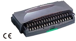
R1C-GH THERMOCOUPLE & DC INPUT MODULE
R1C-GH Remote I/O R1X Series THERMOCOUPLE & DC INPUT MODULE (16 points; CC-Link Ver.1.10/Ver.2.00)
PRODUCTS LIST
- Signal Conditioners
- 2-wire Signal Conditioners
- Power Transducers
- Indicators
- Tower Lights
- Limit Alarms
- Gateway, Remote IO
- Paperless Recording System
- PC Recorder
- Web Data Loggers
- PID Control Components
- BA&Energy Monitoring Components
- Temperature Controllers
- Electric Actuators
- Lightning Surge Protectors
STATISTIC
Visitor: 1063981Online: 24

 Xem ảnh gốc


