R3-WTU MULTI POWER INPUT MODULE
Tình trạng: In stock
Contact: 0989649965
R3-WTU Remote I/O R3 Series MULTI POWER INPUT MODULE (clamp-on current sensor type CLSE use)
Số lượt xem: 1656
Detail
·Some details are not shown. Please refer to specification sheets for all information.
R3-WTU
Remote I/O R3 Series
MULTI POWER INPUT MODULE
(clamp-on current sensor type CLSE use)
Functions & Features
• Measures simultaneously several variables of a heavy-current power system including computing bidirectional current, phase and harmonics
• 1 or 2 systems
• Uses clamp-on current sensors; No need of current transformers
• Current sensors are easy to install in existing systems
Typical Applications
• Energy demand management in manufacturing
plants and buildings
• Multi-functional power monitor incorporated in electric devices or in switching boards: saves space, wiring works, and cost
MODEL: R3–WTU1[1]ES[2]
ORDERING INFORMATION
• Code number: R3-WTU1[1]ES[2]
Specify a code from below for each of [1] and [2].
(e.g. R3-WTU12ES/D/Q)
• Specify the specification for option code /Q
(e.g. /C01)
CONFIGURATION
1: Single-phase / 2-wire and 3-wire,
3-phase / 3-wire and 4-wire
[1] NO. OF SYSTEMS
1: 1 system
2: 2 systems
INPUT
E: 480 V AC / Sensor type CLSE
COMMUNICATION MODE
S: Single
[2] OPTIONS (multiple selections)
Data Capacity (address/slot occupied)
blank: 16 words (1)
/D: 32 words (2)
Be sure to use the R3-BSW base with free address setting
capability. Refer to ‘TRANSMISSION DATA DESCRIPTIONS.’
Other Options
blank: none
/Q: Option other than the above (specify the specification)
SPECIFICATIONS OF OPTION: Q
COATING (For the detail, refer to M-System's web site.)
/C01: Silicone coating
/C02: Polyurethane coating
/C03: Rubber coating
RELATED PRODUCTS
• PC configurator software (model: R3CON)
Downloadable at M-System’s web site.
• Clamp-on current sensor (model: CLSE)
The clamp-on current sensors, not included in this product package, must be ordered separately. Required number depends upon the system configuration.
• Network module (model: R3-Nx, R30Nx)
Data resetting from the host device is possible with: V.2.00 or higher versions of the R3-NC1, R3-NC3, R3-NE1 and
R3-NM1; V.1.06 or higher versions of the R3-NCIE1; and V.1.06 or higher versions of the R30NECT1, R330NCIE1, and R30NE1. (Confirm the firmware version on R3CON.)
For other versions and models, use R3CON PC Configurator to reset data.
For use with the R3-NLx, consult M-System.
GENERAL SPECIFICATIONS
Connection
Internal bus: Via the Installation Base (model: R3-BSx)
Voltage input: Separable terminal block
(applicable wire dia. ≤ 2.5, 0.5 – 3.5 mm2, stripped
length 7 mm)
Current input: Separable terminal block
(applicable wire dia. ≤ 2.4, 0.5 – 3.5 mm2, stripped
length 10 mm)
Internal Power: Via the Installation Base (model: R3-BSx)
Configuration: Single phase/2-wire and 3-wire, 3-phase/3-wire balanced/unbalanced load, 3-phase/4-wire balanced/unbalanced load
Isolation: Sensor core to sensor output or current input or voltage input to internal bus or internal power
Measured variables
Voltage: 1 – N, 2 – N, 3 – N, 1 – 2, 2 – 3, 3 – 1
Current: 1, 2, 3, N
Active / reactive / apparent power: 1, 2, 3, Σ
Power factor: 1, 2, 3, Σ
Frequency
Active energy: Incoming / outgoing
Reactive energy: Incoming / outgoing / lag (inductive)
/lead (capacitive)
Apparent energy
Active / reactive / apparent power intervals (demand)
Average (demand) current: 1, 2, 3, N
Harmonic contents: Σ
Voltage: 1 – N, 2 – N, 3 – N, 1 – 2, 2 – 3, 3 – 1
Current: 1, 2, 3, N
Max. and min. values
Demand history: 1 to 4
(Programmable within 1 – 60 min.; factory set to 30 min.)
RUN indicator: Bi-color (red/green) LED;
Red when the internal bus operates normally.
ERR indicator: Bi-color (red/green) LED;
Red with input abnormality (input ≥ 120 %, frequency out of 45 – 65 Hz range);
Green in normal operating conditions.
Low-end cutout: Converted as 0 % for the input below a preset value; programmable within 0 – 99.9 %; factory set to 1 %
Data resetting: All energy values; MAX / MIN current values; MAX / MIN values other than current; and AVG (demand) values
Data resetting from the host device is possible with: V.2.00 or higher versions of the R3-NC1, R3-NC3, R3-NE1 and
R3-NM1; V.1.06 or higher versions of the R3-NCIE1; and V.1.06 or higher versions of the R30NECT1, R30NCIE1, and R30NE1. (Confirm the firmware version on R3CON.)
INPUT SPECIFICATIONS
Frequency: 50 / 60 Hz (45 – 65 Hz)
• Voltage Input
Rated voltage
Line-to-line (delta voltage): 480 V
Line-neutral (phase voltage): 277 V (single-phase / 2-wire and 3-wire)
Consumption VA: ≤ ULN2 / 300 kΩ / phase
Overload capacity: 200 % of rating for 10 sec., 120 % continuous
Selectable primary voltage range: 50 – 400 000 V
• Current Input
CLSE-R5: 0 – 5 A AC
CLSE-05: 0 – 50 A AC
CLSE-10: 0 – 100 A AC
CLSE-20: 0 – 200 A AC
CLSE-40: 0 – 400 A AC
CLSE-60: 0 – 600 A AC
Overload capacity: 120 % continous, 500 % for 10 sec.
Note: Use for the circuit not exceed 480 V
Selectable primary current range: 1 – 20 000 A (only with CLSE-R5, refer to the configurator settings)
Operational range
Current: 0 – 115 % of the rating
Voltage, apparent power: ≤ 120 % of the rating
Active/reactive power: ±120 % of the rating
Frequency: 45 – 65 Hz
Power factor: ±1
INSTALLATION
Operating temperature: -10 to +55°C (14 to 131°F)
Operating humidity: 30 to 90 %RH (non-condensing)
Atmosphere: No corrosive gas or heavy dust
Mounting: Installation Base (model: R3-BSx)
Use the R3-BSW with Option /D.
Weight: 170 g (0.37 lb)
PERFORMANCE in percentage of span
Accuracy (at 23°C ±10°C or 73.4°F ±18°F, 45 – 65 Hz)
Add the accuracy of the current sensor for overall values.
Voltage: ±1.0 % of the rating
Current: ±1.0 % of the rating
Power: ±1.0 % of the rating
Power factor: ±3.0 %
Frequency: ±1.0 % of the rating
Energy: ±2 %
Harmonic contents: ±2.5 % of the rating
Conversion data: 16 bits / 32 bits
Data allocation mode: 16 or 32
(Refer to ‘TRANSMISSION DATA DESCRIPTIONS.’)
Current consumption: 60 mA
Input response time: ≤ 2 sec. (0 – 100 % ±1 %)
≤3 sec. for frequency and harmonic contents
Insulation resistance: ≥ 100 MΩ with 500 V DC
Dielectric strength: 2000 V AC @ 1 minute (voltage input or current input to internal bus or internal power)
2000 V AC @ 1 minute (sensor core to sensor output)
2000 V AC @ 1 minute (power input to FG; isolated on the power supply module)
TRANSMISSION DATA DESCRIPTIONS
■ MEASURANDS
• 16-word Mode (standard)
Measurands and assigned word numbers are specified using the R3CON PC Configurator.
Max. 16 words per module (slot). 1 word = 16 bits, 2 words
= 32 bits
• 32-word Mode (option /D)
Measurands and assigned word numbers are specified using the R3CON PC Configurator.
Max. 32 words by virtually assigning addresses (n) and (n+1) per module. 1 word = 16 bits, 2 words = 32 bits
Be sure to use the R3-BSW base with free address setting capability. DO NOT assign the address (n+1) to any module.
A duplicate address will cause malfunctions.
■ RESET
Measurands to be reset can be specified among: all energy values, MAX / MIN current values, MAX / MIN values other than current and AVG (demand) values.
Refer to ‘I/O DATA DESCRIPTIONS’ in the R3-WTU instruction manual for resetting from the host device.
For detailed information for the selection of measurands and other settings, refer to the R3CON Users Manual.
EXTERNAL VIEW
EXTERNAL DIMENSIONS unit: mm (inch)
SCHEMATIC CIRCUITRY & CONNECTION DIAGRAM
M-System Co., Ltd.
Products
-
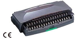
R1MS-GH3 THERMOCOUPLE & DC INPUT MODULE
R1MS-GH3 Remote I/O R1M Series THERMOCOUPLE & DC INPUT MODULE (8 points, isolated)
-
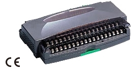
R1M-P4/MSR PC RECORDER
-
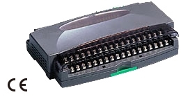
R1M-P4 Remote I/O R1M Series
R1M-P4 Remote I/O R1M Series CONTACT I/O MODULE (4 totalized counter inputs, 8 contact inputs and outputs)
-
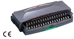
R1M-J3/MSR PC Recorders R1M Series
R1M-J3/MSR PC Recorders R1M Series PC RECORDER (RTD or potentiometer input, 8 points)
-
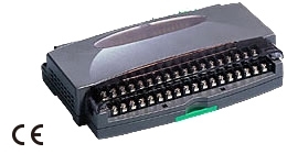
R1M-J3 Remote I/O R1M Series
R1M-J3 Remote I/O R1M Series RTD & POTENTIOMETER INPUT MODULE (8 points)
-
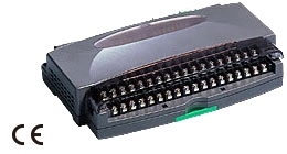
R1M-GH/MSR PC Recorders R1M Series
R1M-GH/MSR PC Recorders R1M Series PC RECORDER (thermocouple or DC input, 16 points)
-
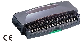
R1MS-GH3/MSR PC Recorders R1M Series
R1MS-GH3/MSR PC Recorders R1M Series PC RECORDER
-
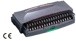
R1D-GH2 THERMOCOUPLE & DC INPUT MODULE
R1D-GH2 Remote I/O R1X Series THERMOCOUPLE & DC INPUT MODULE (16 points; DeviceNet)
-
R1C-GH THERMOCOUPLE & DC INPUT MODULE
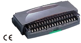
R1C-GH Remote I/O R1X Series THERMOCOUPLE & DC INPUT MODULE (16 points; CC-Link Ver.1.10/Ver.2.00)
PRODUCTS LIST
- Signal Conditioners
- 2-wire Signal Conditioners
- Power Transducers
- Indicators
- Tower Lights
- Limit Alarms
- Gateway, Remote IO
- Paperless Recording System
- PC Recorder
- Web Data Loggers
- PID Control Components
- BA&Energy Monitoring Components
- Temperature Controllers
- Electric Actuators
- Lightning Surge Protectors
STATISTIC
Visitor: 1064659Online: 24

 Xem ảnh gốc


