R3-BA32A BCD CODE INPUT MODULE
Tình trạng: In stock
Contact: 0989649965
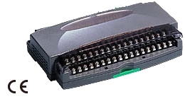
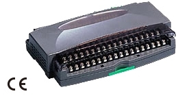
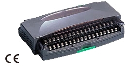
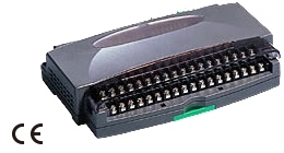
R3-BA32A Remote I/O R3 Series BCD CODE INPUT MODULE (7-digit BCD)
Số lượt xem: 1670
Detail
·Some details are not shown. Please refer to specification sheets for all information.
R3-BA32A
Remote I/O R3 Series
BCD CODE INPUT MODULE
(7-digit BCD)
MODEL: R3–BA32A[1][2]
ORDERING INFORMATION
• Code number: R3-BA32A[1][2]
Specify a code from below for each of [1] and [2].
(e.g. R3-BA32AW/CE/Q)
• Specify the specification for option code /Q
(e.g. /C01)
NO. OF CHANNELS
32: BCD code, 7 digits (4 channels/digit)
EXCITATION SUPPLY
A: External excitation, 24 V DC
[1] COMMUNICATION MODE
S: Single
W: Dual
[2] OPTIONS (multiple selections)
Standards & Approvals
blank: Without CE
/CE: CE marking
Other Options
blank: none
/Q: Option other than the above (specify the specification)
SPECIFICATIONS OF OPTION: Q
COATING (For the detail, refer to M-System's web site.)
/C01: Silicone coating
/C02: Polyurethane coating
/C03: Rubber coating
RELATED PRODUCTS
• Connector terminal block (model: CNT)
• Special cable with 40-pin connector (model: FCN)
GENERAL SPECIFICATIONS
Connection
Internal bus: Via the Installation Base (model: R3-BSx)
Input: 40-pin connector (Fujitsu FCN-365P040-AU)
Internal power: Via the Installation Base (model: R3-BSx)
Isolation: Di 11 thru 28 to Di 31 thru 48 to Di 51 thru 68 to Di 71 thru 88 to internal bus or internal power
Strobe signal control: Selectable with the side DIP switch.
RUN indicator: Bi-color (red/green) LED;
Red when the bus A operates normally;
Green when the bus B operates normally;
Amber when both buses operate normally.
ERR indicator: Green LED turns on in normal operating conditions.
Input status indicator: Red LED; turns on with the input ON.
Group selector: Switches the input status indicator
A. 1 - 8: Di11 - Di28
9 - 16: Di31 - Di48
B. 1 - 8: Di51 - Di68
9 - 16: Di71 - Di88
Read rate: 5 / 10 / 50 / 100 msec. selectable with DIP SW
INPUT SPECIFICATIONS
Number of digits: 7 with strobe signal, 8 without it
Data: 2 words
Data description example
Input data: 1 2 3 4 5 6 7 8
4 high digits 4 low digits
Address 1: 5678 (4 low digits)
Address 2: 1234 (4 high digits)
Input signal: 24 V DC, 32 points (4 points/digit)
Input resistance: 6 kΩ
Isolation: Optical isolator
Common: 4 positive/negative commons, per 8 points
Contact detecting: 24 V DC ±10 %, approx. 4 mA
ON current/resistance: ≥ 2 mA, ≤ 2 kΩ
OFF current/resistance: ≤ 1 mA, ≥ 18 kΩ
INSTALLATION
Operating temperature: -10 to +55°C (14 to 131°F)
Operating humidity: 30 to 90 %RH (non-condensing)
Atmosphere: No corrosive gas or heavy dust
Mounting: Installation Base (model: R3-BSx)
Weight: 150 g (0.33 lb)
PERFORMANCE
Data allocation: 4
Current consumption: 90 mA
Insulation resistance: ≥ 100 MΩ with 500 V DC
Dielectric strength: 2000 V AC @ 1 minute
(Di 11 thru 28 to Di 31 thru 48 to Di 51 thru 68 to Di 71 thru 88 to internal bus or internal power)
2000 V AC @ 1 minute (power input to FG; isolated on the power supply module)
STANDARDS & APPROVALS
EU conformity:
EMC Directive
EMI EN 61000-6-4
EMS EN 61000-6-2
RoHS Directive
EN 50581
FUNCTIONS
■ STROBE SIGNAL CONTROL
Controls the timing of reading data. Data is read in when the strobe signal is ON. No data read while it is OFF, even if there is a status change.
EXTERNAL VIEW
EXTERNAL DIMENSIONS unit: mm (inch)
SCHEMATIC CIRCUITRY & CONNECTION DIAGRAM
INPUT CONNECTOR (40-pin)
M-System Co., Ltd.
Products
-
R1MS-GH3 THERMOCOUPLE & DC INPUT MODULE
R1MS-GH3 Remote I/O R1M Series THERMOCOUPLE & DC INPUT MODULE (8 points, isolated)
-
R1M-P4/MSR PC RECORDER
-
R1M-P4 Remote I/O R1M Series
R1M-P4 Remote I/O R1M Series CONTACT I/O MODULE (4 totalized counter inputs, 8 contact inputs and outputs)
-
R1M-J3/MSR PC Recorders R1M Series
R1M-J3/MSR PC Recorders R1M Series PC RECORDER (RTD or potentiometer input, 8 points)
-
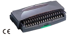
R1M-J3 Remote I/O R1M Series
R1M-J3 Remote I/O R1M Series RTD & POTENTIOMETER INPUT MODULE (8 points)
-
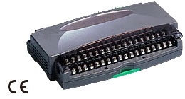
R1M-GH/MSR PC Recorders R1M Series
R1M-GH/MSR PC Recorders R1M Series PC RECORDER (thermocouple or DC input, 16 points)
-
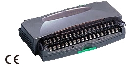
R1MS-GH3/MSR PC Recorders R1M Series
R1MS-GH3/MSR PC Recorders R1M Series PC RECORDER
-
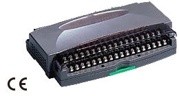
R1D-GH2 THERMOCOUPLE & DC INPUT MODULE
R1D-GH2 Remote I/O R1X Series THERMOCOUPLE & DC INPUT MODULE (16 points; DeviceNet)
-
R1C-GH THERMOCOUPLE & DC INPUT MODULE
R1C-GH Remote I/O R1X Series THERMOCOUPLE & DC INPUT MODULE (16 points; CC-Link Ver.1.10/Ver.2.00)
PRODUCTS LIST
- Signal Conditioners
- 2-wire Signal Conditioners
- Power Transducers
- Indicators
- Tower Lights
- Limit Alarms
- Gateway, Remote IO
- Paperless Recording System
- PC Recorder
- Web Data Loggers
- PID Control Components
- BA&Energy Monitoring Components
- Temperature Controllers
- Electric Actuators
- Lightning Surge Protectors
STATISTIC
Visitor: 1068311Online: 23

 Xem ảnh gốc


