
")
R7I4DECT EtherCAT I/O MODULE


Tình trạng: In stock
Contact: 0989649965
R7I4DECT Remote I/O R7I4D Series EtherCAT I/O MODULE
Số lượt xem: 1125
Detail
·Some details are not shown. Please refer to specification sheets for all information.
R7I4DECT
Remote I/O R7I4D Series
EtherCAT I/O MODULE
MODEL: R7I4DECT-1-[1]-R[2]
ORDERING INFORMATION
• Code number: R7I4DECT-1-[1]-R[2]
Specify a code from below for each of [1] and [2].
(e.g. R7I4DECT-1-DAC32C-R/Q)
• Specify the specification for option code /Q
(e.g. /C01/SET)
TERMINAL BLOCK
1: Tension clamp terminal block for power supply
RJ-45 Modular jack for communication
e-CON connector for I/O
[1] I/O TYPE
DAC32C: NPN discrete input &
NPN transistor output, 16 points each
SVF8N: DC voltage input, high speed, 8 points
(non-isolated)
POWER INPUT
DC Power
R: 24 V DC
(Operational voltage range 24 V ±10 %, ripple 10 %p-p max.)
[2] OPTIONS
blank: none
/Q: With options (specify the specification)
SPECIFICATIONS OF OPTION: Q (multiple selections)
COATING (For the detail, refer to M-System's web site.)
/C01: Silicone coating
/C02: Polyurethane coating
/C03: Rubber coating
EX-FACTORY SETTING
/SET: Preset according to the Ordering Information Sheet
(No. ESU-7779-X)
FUNCTIONS & FEATURES
The R7I4DECT interfaces between I/O signals and a PLC via EtherCAT.
EtherCAT® is a registered trademark and patented technology, licensed by Beckhoff Automation GmbH, Germany.
RELATED PRODUCTS
• PC configurator software (model: R7CFG)
• ESI file
The configurator software and ESI files are downloadable at M-System’s web site.
Use a commercially available Mini-B USB cable to connect the unit to a PC.
GENERAL SPECIFICATIONS
• Common Specifications
Power input: 24 V DC ±10 %; ripple 10 %p-p max.; rated current 8 A
Sensor excitation: 24 V DC ±10 %; ripple 5 %p-p max.,
≤ 5 A (including discrete I/O load charge);
rated current 8 A
Insulation resistance: ≥ 100 MΩ with 500 V DC
Dielectric strength: 1500 V AC @1 minute
(between isolated circuits)
Operating temperature: -10 to +55°C (14 to 131°F)
Operating humidity: 30 to 90 %RH (non-condensing)
Atmosphere: No corrosive gas or heavy dust
Mounting: DIN rail (35 mm wide) or wall
Housing material: Flame-resistant resin (gray)
Status indicator LEDs:
PWR, RUN, ERR, L/A IN, L/A OUT
(Refer to the instruction manual for details.)
Discrete I/O status indicator LEDs:
Green LED on when the contact is ON.
■ Current Consumption & Weight
R7I4DECT-1-DAC32C: Approx. 60 mA/180 g (0.40 lb)
R7I4DECT-1-SVF8N: Approx. 40 mA/170 g (0.37 lb)
(Discrete I/O load charge is not included in the above-mentioned current consumption.)
EtherCAT COMMUNICATION
Standard: IEEE 802.3u
Transmission type: 100BASE-TX
Transmission speed: Full-duplex 100 Mbps
Transmission media: 100BASE-TX (STP cable; Category 5e)
Maximum segment length: 100 meters
Fixed address: Set with rotary switches
(The master must support MDP.)
STANDARDS & APPROVALS
Refer to the manuals to comply with the standards.
EU conformity:
EMC Directive
EMI EN 61000-6-4
EMS EN 61000-6-2
RoHS Directive
EN 50581
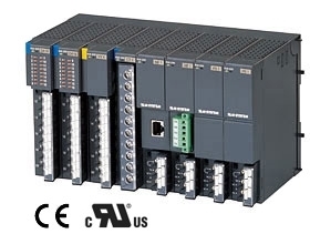
EXTERNAL VIEW
CONNECTION DIAGRAMS
■ I/O connection (Refer to each model terminal assignment)
• e-CON connector
Recommended cable connector: 37104-( )-000FL (3M Company)
(The cable connector is not included in the package.
Specify wire size instead of ( ); refer to the specifications of the product.)
DATA CONVERSION
RESPONSE TIME
• Input module
Response time is time from when a step (0 to 100%) input signal is applied to the input module (slave) until when output from its communication CPU reaches 90% of the final value.
• Output module
Response time is time from when a step (0 to 100%) output signal is received by the communication CPU of the output module (slave) until when its output reaches 90% of the final value.
TCOM: EtherCAT communication cycle set by the host device (master)
(The cycle is determined in accordance with the system configuration and settings.)
TINP: Input module response time ≤ Delay time of input circuit (Ta) + Conversion speed*1 / read cycle (Tb) + Input internal processing time (Tc) (Communication cycle x 2)
TOUT: Output module response time ≤ Delay time of output internal processing (Td) (communication cycle x 1) + Conversion speed*2 (Te) + Delay time of output circuit (Tf)
*1. In case of R7I4DECT-1- SVF8N, Conversion speed x No. of moving averages (1 to 128)
*2. In case of a discrete input/output module, the conversion speed is 0 msec.
ex. 1) R7I4DECT-1-SVF8N
When (No. of moving averages: 1) and EtherCAT communication cycle: 1 msec.,
Input module response time (TINP): Delay time of input circuit (10 msec.) + Conversion speed (2.5 msec.) x No. of moving averages (1) + Input internal processing time (1 msec. x 2) = 14.5 [msec.]
I/O DATA DESCRIPTIONS
Scaling of analog input module is configurable with the configurator software (model: R7CFG). Refer to the software manual for details.
EXTERNAL DIMENSIONS unit: mm (inch)
MOUNTING REQUIREMENTS unit: mm (inch)
M-System Co., Ltd.
Products
-
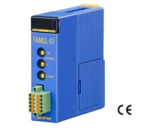
FAMCL-01 CC-Link MASTER MODULE
FAMCL-01 Remote I/O FAM Series CC-Link MASTER MODULE (Yokogawa Electric PLC use)
-
R5-MS POTENTIOMETER INPUT MODULE
R5-MS Remote I/O R5 Series POTENTIOMETER INPUT MODULE
-
R8-SS2 DC CURRENT INPUT MODULE
R8-SS2 Remote I/O R8 Series DC CURRENT INPUT MODULE (2 points, isolated)
-
R3-SS8 DC CURRENT INPUT MODULE
R3-SS8 Remote I/O R3 Series DC CURRENT INPUT MODULE (8 points, isolated)
-

R3-RS8 RTD INPUT MODULE
R3-RS8 Remote I/O R3 Series RTD INPUT MODULE (8 points, isolated)
-

R3-DC32A DISCRETE OUTPUT MODULE
R3-DC32A Remote I/O R3 Series DISCRETE OUTPUT MODULE (Do 32 points; open collector)
-

R30SV4 DC VOLTAGE/CURRENT INPUT MODULE
R30SV4 Remote I/O R30 Series DC VOLTAGE/CURRENT INPUT MODULE (4 points, isolated)
-
R3-DC16C DISCRETE OUTPUT MODULE
R3-DC16C Remote I/O R3 Series DISCRETE OUTPUT MODULE (PNP transistor output, 16 points)
-

R3-MS4 POTENTIOMETER INPUT MODULE
R3-MS4 Remote I/O R3 Series POTENTIOMETER INPUT MODULE (4 points, isolated)
PRODUCTS LIST
- Signal Conditioners
- 2-wire Signal Conditioners
- Power Transducers
- Indicators
- Tower Lights
- Limit Alarms
- Gateway, Remote IO
- Paperless Recording System
- PC Recorder
- Web Data Loggers
- PID Control Components
- BA&Energy Monitoring Components
- Temperature Controllers
- Electric Actuators
- Lightning Surge Protectors
News Product
 IT40SW5F/6F, IT50SW5F/6F, IT60SW5F/6F Series")


STATISTIC
Visitor: 1062582Online: 29

