
")
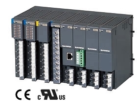
R7G4HML MECHATROLINK I/O MODULE


Tình trạng: In stock
Contact: 0989649965
R7G4HH-A-YVF4 Remote I/O R7G4H Series HI-SPEED LINK SYSTEM I/O MODULE
Số lượt xem: 1506
Detail
·Some details are not shown. Please refer to specification sheets for all information.
R7G4HH-A-YVF4
Remote I/O R7G4H Series
HI-SPEED LINK SYSTEM I/O MODULE
(HLS-compatible, high-speed DC voltage output, 4 points, isolated, screw terminal block)
Functions & Features
• High-speed DC voltage/current output via HLS
• Easy parameter setting of individual channels with M-System's configurator software
HLS is the abbreviation for “Hi-speed Link System” of Step Technica Co., Ltd.
MODEL: R7G4HH-A-YVF4-R[1]
ORDERING INFORMATION
• Code number: R7G4HH-A-YVF4-R[1]
Specify a code from below for [1].
(e.g. R7G4HH-A-YVF4-R/H/E/Q)
• Specify the specification for option code /Q
(e.g. /C01/SET)
TERMINAL BLOCK
A: Screw terminal block for power supply
RJ-45 Modular jack for communication
Screw terminal block for I/O
I/O TYPE
YVF4: DC voltage output, high speed, 4 points
POWER INPUT
DC power
R: 24 V DC
(Operational voltage range: ±10 %; ripple 10 %p-p max.)
[1] OPTIONS (multiple selections)
Communication Mode
blank: Full-duplex
/H: Half-duplex
Communication Connector Pin Assignment
Blank: 3, 4 - 5, 6 pair wiring
(M-System HLS related device standard pin assignment)
/E: 4, 5 - 3, 6 pair wiring (Ethernet cable pin assignment)
Other Options
blank: none
/Q: Option other than the above (specify the specification)
SPECIFICATIONS OF OPTION: Q (multiple selections)
COATING (For the detail, refer to M-System's web site.)
/C01: Silicone coating
/C02: Polyurethane coating
/C03: Rubber coating
EX-FACTORY SETTING
/SET: Preset according to the Ordering Information Sheet
(No. ESU-7777-YVF4)
RELATED PRODUCTS
• PC configurator software (model: R7CFG)
Downloadable at M-System’s web site.
A dedicated cable is required to connect the module to the PC. Please refer to the internet software download site or the users manual for the PC configurator for applicable cable types.
GENERAL SPECIFICATIONS
Connection
HLS: RJ-45 Modular Jack
Power & Output: M3 separable screw terminals
(torque 0.5 N·m)
Screw terminal material: Nickel-plated steel
Solderless terminal: Refer to the drawing at the end of the section.
Recommended manufacturer: Japan Solderless Terminal MFG.Co.Ltd, Nichifu Co.,ltd
Applicable wire size: 0.25 to 1.65 mm2 (AWG 22 to 16)
Housing material: Flame-resistant resin (gray)
Isolation: Output 0 to Output 1 to Output 2 to Output 3 to HLS or FE to Power
Output bias adjustment: Configurable via R7CFG
Output gain adjustment: Configurable via R7CFG
Output range: Selectable with the DIP SW on the top of the unit or configurable via R7CFG
Output at the loss of communication: Selectable with the DIP SW on the top of the unit or configurable via R7CFG
Output reset value: Configurable via R7CFG
Indicator LEDs: PWR and ERR LEDs indicate operating conditions of the unit. (Refer to the insruction manual for detail)
HLS COMMUNICATION
Communication mode: Full-duplex or half-duplex
Network cable
•Shield cable
Full-duplex communication:
ZHY262PS / ZHT262PS (Shinko Seisen Industry Co., Ltd.)
Half-duplex communication:
ZHY221PS (Shinko Seisen Industry Co., Ltd.)
•Dual-shield cable
ZHY262PBA (Shinko Seisen Industry Co., Ltd.)
Transmission distance:
12 Mbps: 100 meters (328 ft)
6 Mbps: 200 meters (656 ft)
(Baud rate configurable with DIP SW; factory default: 12 Mbps)
Note) The above transmission distance is a reference value when the HLS master unit is one-to-one connected to the HLS slave unit (R4GHH) with a designated double shielded cable. The actual distance may differ depending on the system configuration (types of the master/slave units, communication cable, the number of slaves connected, etc.), settings, and/or the installation environment.
Terminating resistor: Built-in (Selected with the DIP SW; factory default: disabled)
Status indicator: RUN
(Refer to the instruction manual for details.)
Station address: Selectable with rotary switch
(Refer to the instruction manual for details.)
OUTPUT SPECIFICATIONS
■ Load resistance: 100 kΩ min.
■ Narrow Span voltage: -1 – +1 V, 0 – 1 V DC,
-0.5 – +0.5 V DC
■ Wide Span voltage: -10 – +10 V, -5 – +5 V, 0 – 10 V,
0 – 5 V, 1 – 5 V DC
■ Output Range
Except -10 to +10 V DC: -15 to +115 % of output range
-10 to +10 V DC: Approx. -11.5 to +11.5 V DC
INSTALLATION
Current consumption
•DC: Approx. 70 mA
Operating temperature: -10 to +55°C (14 to 131°F)
Operating humidity: 30 to 90 %RH (non-condensing)
Atmosphere: No corrosive gas or heavy dust
Mounting: Surface or DIN rail (35 mm rail)
Weight: 210 g (0.46 lb)
PERFORMANCE
Conversion accuracy: ±0.1 %
Conversion rate: 200 μsec. per 4 channels
Data range: 0 – 10000 of the output range
Temp. coefficient: ±0.015 %/°C (±0.008 %/°F)
Output delay time: ≤ 250 μs (0 - 90 %)
Insulation resistance: ≥ 100 MΩ with 500 V DC
Dielectric strength: 1500 V AC @ 1 minute
Output 0 to Output 1 to Output 2 to Output 3 to HLS or FE to power
STANDARDS & APPROVALS
EU conformity:
EMC Directive
EMI EN 61000-6-4
EMS EN 61000-6-2
RoHS Directive
EN 50581
PC CONFIGURATOR
The following parameters can be set with using PC Configurator Software (model: R7CFG)
Refer to the users manual for the R7CFG for detailed operation of the software program.
EXTERNAL VIEW
CONNECTION DIAGRAMS
TERMINAL ASSIGNMENTS
DATA CONVERSION
RESPONSE TIME
Response time of analog output module (R7G4HH-A-YVF4; slave) is time from when 0 to 100% stepwise signal change is received by the communication ASIC of the module till when the analog output signal reaches 90%.
TCOM: HLS scan time
HLS scan time varies according to communication method, the number of operating slave stations (FS), transmission rate (TBPS), and the hop count (LF).
· Full-duplex communication
LF = 0 : HLS scan time = 182 x FS x TBPS (sec.)
LF = 1 to 7: HLS scan time = (184 + (144 x LF)) x FS x TBPS (sec.)
· Half-duplex communication
LF = 0 : HLS scan time = 354 x FS x TBPS (sec.)
LF = 1 to 7: HLS scan time = (328 + (144 x LF)) x FS x TBPS (sec.)
TOUT: Output unit response time ≤ Delay time of output internal processing (Td) (HLS scan time) + Conversion rate (Te) + Delay time of output circuit (Tf)
e.g.
Communication: Full-duplex,
Number of operating slave station (FS): 63,
Transmission rate (TBPS): 12 Mbps,
The hop count (LF): 0,
HLS scan time (TCOM): 182 x 63 x 1 / 12 M = 0.9555 [msec.]
Output unit response time (TINP): Delay time of output internal processing (0.9555 msec.) + Conversion rate (0.2 msec.) + Delay time of output circuit (0.25 msec.) = 1.4 [msec.]
I/O DATA DESCRIPTIONS
Scaling of analog output module is configurable with the configurator software (model: R7CFG). Refer to the software manual for details.
EXTERNAL DIMENSIONS & TERMINAL ASSIGNMENTS unit: mm (inch)
MOUNTING REQUIREMENTS unit: mm (inch)
SCHEMATIC CIRCUITRY & CONNECTION DIAGRAM
Note: In order to improve EMC performance, bond the FE terminal to ground.
Caution: FE terminal is NOT a protective conductor terminal.
M-System Co., Ltd.
Products
-
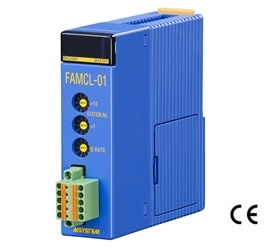
FAMCL-01 CC-Link MASTER MODULE
FAMCL-01 Remote I/O FAM Series CC-Link MASTER MODULE (Yokogawa Electric PLC use)
-
R5-MS POTENTIOMETER INPUT MODULE
R5-MS Remote I/O R5 Series POTENTIOMETER INPUT MODULE
-
R8-SS2 DC CURRENT INPUT MODULE
R8-SS2 Remote I/O R8 Series DC CURRENT INPUT MODULE (2 points, isolated)
-
R3-SS8 DC CURRENT INPUT MODULE
R3-SS8 Remote I/O R3 Series DC CURRENT INPUT MODULE (8 points, isolated)
-

R3-RS8 RTD INPUT MODULE
R3-RS8 Remote I/O R3 Series RTD INPUT MODULE (8 points, isolated)
-

R3-DC32A DISCRETE OUTPUT MODULE
R3-DC32A Remote I/O R3 Series DISCRETE OUTPUT MODULE (Do 32 points; open collector)
-

R30SV4 DC VOLTAGE/CURRENT INPUT MODULE
R30SV4 Remote I/O R30 Series DC VOLTAGE/CURRENT INPUT MODULE (4 points, isolated)
-
R3-DC16C DISCRETE OUTPUT MODULE
R3-DC16C Remote I/O R3 Series DISCRETE OUTPUT MODULE (PNP transistor output, 16 points)
-

R3-MS4 POTENTIOMETER INPUT MODULE
R3-MS4 Remote I/O R3 Series POTENTIOMETER INPUT MODULE (4 points, isolated)
PRODUCTS LIST
- Signal Conditioners
- 2-wire Signal Conditioners
- Power Transducers
- Indicators
- Tower Lights
- Limit Alarms
- Gateway, Remote IO
- Paperless Recording System
- PC Recorder
- Web Data Loggers
- PID Control Components
- BA&Energy Monitoring Components
- Temperature Controllers
- Electric Actuators
- Lightning Surge Protectors
News Product
 IT40SW5F/6F, IT50SW5F/6F, IT60SW5F/6F Series")


STATISTIC
Visitor: 1078456Online: 13

