
")
R7G4FML3 MECHATROLINK I/O MODULE


Tình trạng: In stock
Contact: 0989649965
Số lượt xem: 1489
Detail
·Some details are not shown. Please refer to specification sheets for all information.
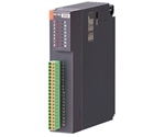
R7G4FML3
Remote I/O R7G4F Series
MECHATROLINK I/O MODULE
(MECHATROLINK-III)
MODEL: R7G4FML3-[1]-[2]-R[3]
ORDERING INFORMATION
• Code number: R7G4FML3-[1]-[2]-R[3]
Specify a code from below for each [1] through [3].
(e.g. R7G4FML3-6-DC16A-R/UL/Q)
• Specify the specification for option code /Q
(e.g. /C01)
[1] TERMINAL BLOCK
6: Screw terminal block for power supply
Connector for MECHATROLINK- III
Screw terminal block for I/O
B: Tension clamp terminal block for power supply
Connector for MECHATROLINK- III
e-CON connector for I/O
[2] I/O TYPE
DA16: NPN/PNP discrete input, 16 points
DA16A: NPN discrete input, 16 points
(Option /UL Not selectable)
DC16A: NPN transistor output, 16 points
DC16B: PNP transistor output, 16 points
POWER INPUT
DC power
R: 24 V DC
(Operational voltage range: ±10 %; ripple 10 %p-p max.)
[3] OPTIONS (multiple selections)
Standards & Approvals
blank: CE marking
/UL: UL approval, CE marking
Other Options
blank: none
/Q: Option other than the above (specify the specification)
SPECIFICATIONS OF OPTION: Q
COATING (For the detail, refer to M-System's web site.)
/C01: Silicone coating
/C02: Polyurethane coating
/C03: Rubber coating (UL not available)
FUNCTIONS & FEATURES
MECHATROLINK I/O module (this module), interfaces discrete I/Os and PLC or PC via MECHATROLINK-III.
Removable terminal blocks make the module replaceable without disconnection of wiring
RELATED PRODUCTS
• PC configurator software (model: R7CFG)
Downloadable at M-System’s web site.
A dedicated cable is required to connect the module to the PC. Please refer to the internet software download site or the users manual for the PC configurator for applicable cable types.
GENERAL SPECIFICATIONS
• Common Specifications
Power input: 24 V DC ±10 %; ripple 10 %p-p max.
Insulation resistance: ≥ 100 MΩ with 500 V DC
Dielectric strength: 1500 V AC @1 minute
(between isolated circuits)
Operating temperature: -10 to +55°C (14 to 131°F)
Operating humidity: 30 to 90 %RH (non-condensing)
Atmosphere: No corrosive gas or heavy dust
Storage temperature: -20 to +65°C (-4 to +149°F)
Mounting: DIN rail (35 mm wide) or wall
Housing material: Flame-resistant resin (gray)
Status indicator LEDs: PWR, ERR, CON, LNK1, LNK2
(Refer to the instruction manual for details)
■ Current Consumption & Weight
R7G4FML3-6-DA16: 75 mA, 190 g (0.42 lb)
R7G4FML3-B-DA16A: 75 mA, 130 g (0.29 lb)
R7G4FML3-6-DC16A: 80 mA, 190 g (0.42 lb)
R7G4FML3-6-DC16B: 80 mA, 190 g (0.42 lb)
(Discrete I/O load charge is not included in the above-mentioned current consumption.)
MECHATROLINK-III COMMUNICATION
Baud rate: 100 Mbps
Transmission distance: 6300 m max.
Distance between stations: 100 m max.
Transmission media: MECHATROLINK cable (Model JEPMC-W6013-x-E, Yaskawa Controls Co., Ltd.)
Connector: TYCO AMP Industrial mini I/O connector
Max. number of slaves: 62
(The maximum number of slaves might change depending on the master unit. Refer to the manual of the master unit)
Transmission cycle: 125 µsec., 250 µsec., 500 µsec., 1 – 64 msec. (with 1 msec. increments)
Communication cycle: 125 µsec. through 64 msec.
Applicable profile: Standard I/O profile (cyclic communication)
Event-driven communication acquiring ID profile (event-driven communication)
Transmission bytes: 16 bytes
Station address: 03H through EFH (set with rotary switches)
Cyclic communication: Available
Event-driven communication: Available
Slave monitoring: None
STANDARDS & APPROVALS
Refer to the manuals to comply with the standards.
EU conformity:
EMC Directive
EMI EN 61000-6-4
EMS EN 61000-6-2
RoHS Directive
EN 50581
Safety approval:
UL/C-UL general safety requirements
(UL 61010-1, CAN/CSA-C22.2 No.61010-1-12)
(UL 61010-2-201, CAN/CSA-C22.2 No.61010-2-201)
EXTERNAL VIEW
CONNECTION DIAGRAMS
MECHATROLINK RELATED COMMANDS
RESPONSE TIME
Response time of discrete input module is the time till when the unit starts sending to a transmission line when a signal is applied to the input module.
Response time of discrete output module is the time till when the module outputs a signal when the unit completes receiving from a transmission line.
TCOM: MECHATROLINK-III transmission cycle configured by a host device.
MECHATROLINK-III transmission cycle vavies depends on system and configuration.
TINP: Response time of input module ≤ Ta Delay of input circuit (ON delay time or OFF delay time) +
Tb Read rate setting time +
Tc Internal processing delay time (2 cycle of MECHATROLINK-III transmission cycle)
T0UT: Response time of output module ≤ Td Internal processing delay time (1 cycle of min. transmission cycle units can handle)
+ Te Delay of output circuit (ON delay time or OFF delay time)
E.g. 1. DA16 module: Read rate of 1 msec., MECHATROLINK-III transmission cycle of 0.25 msec.
Response time of input module (TINP): Delay of input circuit (0.2 msec.) + Read rate setting time (1 msec.) +
Internal processing delay time (0.25 msec.) x 2 = 1.7 [msec.]
E.g. 2. DA16 module: MECHATROLINK-III transmission cycle of 0.5 msec.
Response time of output module (T0UT): Internal processing delay time (0.125 msec.) + Delay of output circuit (0.5 msec.)
= 0.625 [msec.]
I/O DATA DESCRIPTIONS
DIMENSIONS unit: mm (inch)
MOUNTING REQUIREMENTS unit: mm (inch)
M-System Co., Ltd.
Products
-
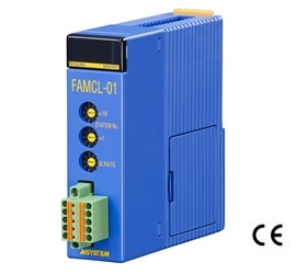
FAMCL-01 CC-Link MASTER MODULE
FAMCL-01 Remote I/O FAM Series CC-Link MASTER MODULE (Yokogawa Electric PLC use)
-
R5-MS POTENTIOMETER INPUT MODULE
R5-MS Remote I/O R5 Series POTENTIOMETER INPUT MODULE
-
R8-SS2 DC CURRENT INPUT MODULE
R8-SS2 Remote I/O R8 Series DC CURRENT INPUT MODULE (2 points, isolated)
-
R3-SS8 DC CURRENT INPUT MODULE
R3-SS8 Remote I/O R3 Series DC CURRENT INPUT MODULE (8 points, isolated)
-

R3-RS8 RTD INPUT MODULE
R3-RS8 Remote I/O R3 Series RTD INPUT MODULE (8 points, isolated)
-

R3-DC32A DISCRETE OUTPUT MODULE
R3-DC32A Remote I/O R3 Series DISCRETE OUTPUT MODULE (Do 32 points; open collector)
-

R30SV4 DC VOLTAGE/CURRENT INPUT MODULE
R30SV4 Remote I/O R30 Series DC VOLTAGE/CURRENT INPUT MODULE (4 points, isolated)
-
R3-DC16C DISCRETE OUTPUT MODULE
R3-DC16C Remote I/O R3 Series DISCRETE OUTPUT MODULE (PNP transistor output, 16 points)
-

R3-MS4 POTENTIOMETER INPUT MODULE
R3-MS4 Remote I/O R3 Series POTENTIOMETER INPUT MODULE (4 points, isolated)
PRODUCTS LIST
- Signal Conditioners
- 2-wire Signal Conditioners
- Power Transducers
- Indicators
- Tower Lights
- Limit Alarms
- Gateway, Remote IO
- Paperless Recording System
- PC Recorder
- Web Data Loggers
- PID Control Components
- BA&Energy Monitoring Components
- Temperature Controllers
- Electric Actuators
- Lightning Surge Protectors
News Product
 IT40SW5F/6F, IT50SW5F/6F, IT60SW5F/6F Series")


STATISTIC
Visitor: 1078105Online: 18

