
")
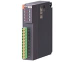
R3-NL1 LonWorks INTERFACE MODULE


Tình trạng: In stock
Contact: 0989649965
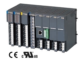
R3-NL1 Remote I/O R3 Series LonWorks INTERFACE MODULE (analog I/O 16 points, discrete I/O 48 points)
Số lượt xem: 1696
Detail
·Some details are not shown. Please refer to specification sheets for all information.
R3-NL1
Remote I/O R3 Series
LonWorks INTERFACE MODULE
(analog I/O 16 points, discrete I/O 48 points)
MODEL: R3–NL1–[1][2]
ORDERING INFORMATION
• Code number: R3-NL1-[1][2]
Specify a code from below for each of [1] and [2].
(e.g. R3-NL1-R/Q)
• Specify the specification for option code /Q
(e.g. /C01)
[1] POWER INPUT
N: No power supply
AC Power
K3: 100 – 120 V AC
(Operational voltage range 85 - 132 V, 47 - 66 Hz) *
L3: 200 – 240 V AC
(Operational voltage range 170 - 264 V, 47 - 66 Hz) *
DC Power
R: 24 V DC
(Operational voltage range 24 V ±10 %, ripple 10 %p-p max.) *
* Not selectable for use with independent power modules or network modules with the internal power input options.
[2] OPTIONS
blank: none
/Q: With options (specify the specification)
SPECIFICATIONS OF OPTION: Q
COATING (For the detail, refer to M-System's web site.)
/C01: Silicone coating
/C02: Polyurethane coating
/C03: Rubber coating
RELATED PRODUCTS
• XIF File (Device Interface File)
XIF file is used to define a LonWorks device when programmed on LonMaker.
GENERAL SPECIFICATIONS
Connection
LonWorks: Euro type connector terminal
(applicable wire size: 0.2 to 2.5 mm2, stripped length 7 mm)
Internal bus: Via the Installation Base
(model: R3-BSx)
Internal power: Via the Installation Base (model: R3-BSx)
Power input, RUN contact output: M3 separable screw terminal (torque 0.5 N·m)
Screw terminal: Nickel-plated steel
Isolation: LonWorks to internal bus or internal power to power input to RUN contact output to FG
Input error data setting: Input value setting at input module error with side DIP SW
Dual communication setting: Set with the side DIP switch
Data allocation setting: Set with the side DIP switch
RUN indicator: Bi-color (green/red) LED; Green ON in communications with another device online or changing the output data (turns off after 25 seconds of no communication); Red ON when receiving data (function selected with DIP SW)
ERR indicator: Bi-color (green/red) LED; Green ON or blinking at communication error; Red ON at transmitting data (Function selected with DIP SW)
■ RUN CONTACT OUTPUT
RUN contact: Turns on while the green RUN LED is ON (LonWorks in normal communication)
Rated load: 250 V AC @ 0.5 A (cos ø = 1)
30 V DC @ 0.5 A (resistive load)
Maximum switching voltage: 250 V AC or 30 V DC
Maximum switching power: 250 VA or 150 W
Minimum load: 1 V DC @ 1 mA
Mechanical life: 2 × 10⁷ cycles (rate 300 cycles/min.) When driving an inductive load, external contact protection and noise quenching recommended.
LonWorks COMMUNICATION
Neuron Chip: FT3120 (NeuronID printed in numbers and bar code [peel-off code 39 format])
Transceiver: FT-X1 (equivalent to FTT10A)
Transmission speed: 78 kbps
Twisted-pair cable
Distance, free topology: 500 meters
Max. 64 nodes/channel
LNS: Ver. 3.0 Service Pack 8 or higher
Network variable type
Analog: SNVT_lev_percent or SNVT_temp (selectable)
Discrete: SNVT_switch
ONLINE indicator: Red LED
ON: Off-line or no network information (decommissioned)
Blinking in approx. 0.5 Hz: On-line
(ready to communicate network variables)
Blinking in approx. 5 Hz for 30 sec.: Wink message received
SERVICE indicator: Green LED
OFF: Normal operations
Blinking in approx. 0.5 Hz: No network information
ON: Internal program error
SERVICE switch: Used to identify the node in LonWorks
network configuration
RESET switch: Resetting the Neuron Chip
INSTALLATION
Power consumption
•AC: Approx. 20 VA
•DC: Approx. 12 W
Current consumption (no power supply): 100 mA
Output current (power supply): 250 mA continuous at 20 V DC; 400 mA for 10 minutes
Operating temperature: -10 to +55°C (14 to 131°F)
Operating humidity: 30 to 90 %RH (non-condensing)
Atmosphere: No corrosive gas or heavy dust
Mounting: Installation Base (model: R3-BSx)
Weight: 200 g (0.44 lb)
PERFORMANCE
Insulation resistance: ≥ 100 MΩ with 500 V DC
Dielectric strength: 1500 V AC @ 1 minute (LonWorks or internal bus or internal power to power input to RUN contact output to FG)
EXTERNAL VIEW
COMMUNICATION CABLE CONNECTIONS
TRANSMISSION DATA DESCRIPTIONS
I/O COMBINATIONS
A dedicated Device File for each I/O device depending upon I/O combinations is required using an integration tool such as Lon Maker.
On-line download is available for Device Image files at M-System's homepage.
Functional Blocks usable for respective files are not identical to all. Refer to the manual.
EXTERNAL DIMENSIONS & TERMINAL ASSIGNMENTS unit: mm (inch)
SCHEMATIC CIRCUITRY & CONNECTION DIAGRAM
Caution: FG terminal is NOT a protective conductor terminal.
M-System Co., Ltd.
Products
-
FAMCL-01 CC-Link MASTER MODULE
FAMCL-01 Remote I/O FAM Series CC-Link MASTER MODULE (Yokogawa Electric PLC use)
-
R5-MS POTENTIOMETER INPUT MODULE
R5-MS Remote I/O R5 Series POTENTIOMETER INPUT MODULE
-
R8-SS2 DC CURRENT INPUT MODULE
R8-SS2 Remote I/O R8 Series DC CURRENT INPUT MODULE (2 points, isolated)
-
R3-SS8 DC CURRENT INPUT MODULE
R3-SS8 Remote I/O R3 Series DC CURRENT INPUT MODULE (8 points, isolated)
-

R3-RS8 RTD INPUT MODULE
R3-RS8 Remote I/O R3 Series RTD INPUT MODULE (8 points, isolated)
-

R3-DC32A DISCRETE OUTPUT MODULE
R3-DC32A Remote I/O R3 Series DISCRETE OUTPUT MODULE (Do 32 points; open collector)
-

R30SV4 DC VOLTAGE/CURRENT INPUT MODULE
R30SV4 Remote I/O R30 Series DC VOLTAGE/CURRENT INPUT MODULE (4 points, isolated)
-
R3-DC16C DISCRETE OUTPUT MODULE
R3-DC16C Remote I/O R3 Series DISCRETE OUTPUT MODULE (PNP transistor output, 16 points)
-

R3-MS4 POTENTIOMETER INPUT MODULE
R3-MS4 Remote I/O R3 Series POTENTIOMETER INPUT MODULE (4 points, isolated)
PRODUCTS LIST
- Signal Conditioners
- 2-wire Signal Conditioners
- Power Transducers
- Indicators
- Tower Lights
- Limit Alarms
- Gateway, Remote IO
- Paperless Recording System
- PC Recorder
- Web Data Loggers
- PID Control Components
- BA&Energy Monitoring Components
- Temperature Controllers
- Electric Actuators
- Lightning Surge Protectors
News Product
 IT40SW5F/6F, IT50SW5F/6F, IT60SW5F/6F Series")


STATISTIC
Visitor: 1061606Online: 17

