
")
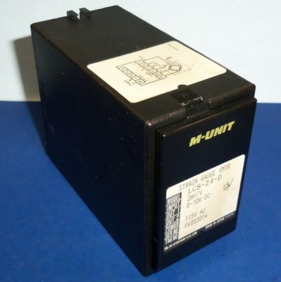
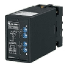
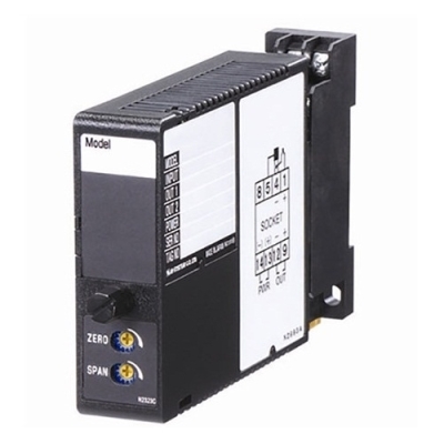
MXLCF STRAIN GAUGE TRANSMITTER


Tình trạng: In stock
Contact: 0989649965
MXLCF STRAIN GAUGE TRANSMITTER
Số lượt xem: 1749
Detail
PRODUCTS LIST
- Signal Conditioners
- 2-wire Signal Conditioners
- Power Transducers
- Indicators
- Tower Lights
- Limit Alarms
- Gateway, Remote IO
- Paperless Recording System
- PC Recorder
- Web Data Loggers
- PID Control Components
- BA&Energy Monitoring Components
- Temperature Controllers
- Electric Actuators
- Lightning Surge Protectors
News Product
 IT40SW5F/6F, IT50SW5F/6F, IT60SW5F/6F Series")


STATISTIC
Visitor: 1050805Online: 21

