

")
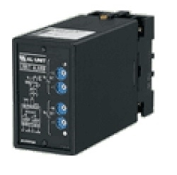
STRAIN GAUGE TRANSMITTER LCS SERIES


Tình trạng: In stock
Contact: 0989649965
Số lượt xem: 1101
Detail
Model: LCS-2A-H/E2
STRAIN GAUGE TRANSMITTER
(isolated)
Functions & Features
• Providing a DC output signal proportional to a bridge type strain gauge utilized in load cells, pressure transducers
• Supplying required excitation voltage
• Drives bridges 80 Ω or above
• Excitation adjustable from 2 V to 10 V
• Wide-range adjustment: 0 – 80 % for zero, 20 – 100 % for span
• Fast response type available
• LCD meter (engineering unit display selectable)
• Simple loop test output (0 % and 100 %)
• High-density mounting
Typical Applications
• Weighing system for tanks, hoppers, silos
• Weighing system using cranes
• Float level meter utilizing strain gauges
MODEL: LCS–[1][2]–[3][4]
ORDERING INFORMATION
• Code number: LCS-[1][2]-[3][4]
Specify a code from below for each of [1] through [4].
(e.g. LCS-2A-B/E2/Q)
• Special output range (For codes Z & 0)
• Specify the specification for option code /Q
(e.g. /C01/S01)
[1] INPUT STRAIN GAUGE
1: 1 mV/V
12: 1.25 mV/V
15: 1.5 mV/V
2: 2 mV/V
3: 3 mV/V
4: 4 mV/V
5: 5 mV/V
6: 10 mV/V
7: 20 mV/V
0: Specify (strain gauge and excitation)
[2] OUTPUT
Current
A: 4 – 20 mA DC (Load resistance 750 Ω max.)
B: 2 – 10 mA DC (Load resistance 1500 Ω max.)
C: 1 – 5 mA DC (Load resistance 3000 Ω max.)
D: 0 – 20 mA DC (Load resistance 750 Ω max.)
E: 0 – 16 mA DC (Load resistance 900 Ω max.)
F: 0 – 10 mA DC (Load resistance 1500 Ω max.)
G: 0 – 1 mA DC (Load resistance 15 kΩ max.)
Z: Specify current (See OUTPUT SPECIFICATIONS)
Voltage
1: 0 – 10 mV DC (Load resistance 10 kΩ min.)
2: 0 – 100 mV DC (Load resistance 100 kΩ min.)
3: 0 – 1 V DC (Load resistance 100 Ω min.)
4: 0 – 10 V DC (Load resistance 1000 Ω min.)
5: 0 – 5 V DC (Load resistance 500 Ω min.)
6: 1 – 5 V DC (Load resistance 500 Ω min.)
4W: -10 – +10 V DC (Load resistance 2000 Ω min.)
5W: -5 – +5 V DC (Load resistance 1000 Ω min.)
0: Specify voltage (See OUTPUT SPECIFICATIONS)
[3] POWER INPUT
AC Power
B: 100 V AC
C: 110 V AC
D: 115 V AC
F: 120 V AC
G: 200 V AC
H: 220 V AC
J: 240 V AC
DC Power
R: 24V DC (Not selectable with option /E or /E2)
[4] OPTIONS (multiple selections)
Input Signal Indicator
blank: Without
/E: With (0.0 - 100.0 % display)
/E2: With (in engineering unit with backlight and the
simple loop test output)
Response Time (0 – 90 %)
blank: Standard (≤ 0.5 sec.)
/K: Fast response (Approx. 25 msec.)
(Not selectable with Option /E2)
Other Options
blank: none
/Q: Option other than the above (specify the specification)
SPECIFICATIONS OF OPTION: Q (multiple selections)
COATING (For the detail, refer to M-System's web site.)
/C01: Silicone coating
/C02: Polyurethane coating
/C03: Rubber coating
TERMINAL SCREW MATERIAL
/S01: Stainless steel
GENERAL SPECIFICATIONS
Construction: Plug-in
Connection: M3.5 screw terminals
Screw terminal: Chromated steel (standard) or stainless steel
Housing material: Flame-resistant resin (black)
Isolation: Input to output to power
Overrange output: Approx. -10 to +120 % at 1 – 5 V
Excitation adjustment: 2 – 10 V (front)
Zero adjustments (tare): 0 – 80 % (front)
(Excitation voltage: factory default)
Span adjustment: 100 – 20 % (front)
(Excitation voltage: factory default)
Simple loop test output: 0 % and 100 % signal simulated by selecting the front switch positions. (Only for option code /E2)
■ DISPLAY (Input indicator)
• Option code: /E
LCD digital display: 0.0 - 100.0 % (min. digit 0.1 %)
(No scaling)
• Option code: /E2
LCD digital display: Engineering unit
Display scaling: -10000 – +10000
Decimal position: 10-1 - 10-4 or no decimal point
Engineering unit: %, μV, mV, V, mA, A, °C, °F, Ω, DEG K, mHz, Hz, kHz, VAC, AAC, mg, g, kg, t, rpm or rps selectable
Back light: Green at normal, red at loop test output enable
Factory setting: scaling 0.00 - 100.00, unit: %
INPUT SPECIFICATIONS
■ Input: Bridge voltage from load cells
• Strain Gauge
Rated output from strain gauge: 1 – 20 mV/V;
Input to the transmitter must be over 3 mV.
• Excitation: 2 – 10 V adjustable (5 V standard)
Maximum current: 35 mA at 10 V, 65 mA at ≤ 7.5 V
OUTPUT SPECIFICATIONS
■ DC Current: 0 – 20 mA DC
Minimum span: 1 mA
Offset: Max. 1.5 times span
Load resistance: Output drive 15 V max.
■ DC Voltage: -10 – +12 V DC
Minimum span: 5 mV
Offset: Max. 1.5 times span
Load resistance: Output drive 10 mA max.; 5 mA for negative voltage output; at ≥ 0.5 V
INSTALLATION
Power input
•AC: Operational voltage range: rating ±10 %, 50/60 ±2 Hz, approx. 3 VA
(approx. 4 VA with Option /E2)
•DC: Operational voltage range: 24 V ±10 %,
approx. 150 mA, ripple 10 %p-p max.
Operating temperature: -5 to +60°C (23 to 140°F)
Operating humidity: 30 to 90 %RH (non-condensing)
Mounting: Surface or DIN rail
Weight: 430 g (0.95 lb)
PERFORMANCE in percentage of span
Accuracy: ±0.1 % (input ≥ 3 mV)
Display accuracy: ± (0.1 % of FS + 1 digit)
(input ≥ 3 mV)
Simple loop test output setting accuracy: ±0.5 %
Temp. coefficient: ±0.015 %/°C (±0.008 %/°F)
Line voltage effect: ±0.1 % over voltage range
Insulation resistance: ≥ 100 MΩ with 500 V DC
Dielectric strength: 2000 V AC @1 minute for AC power
1000 V AC @1 minute for DC power
(input or output to power)
1000 V AC @1 minute (input to output)
2000 V AC @1 minute
(input or output or power to ground)
Model: LCS-2A-H/E2
-------------------------------------
CÔNG TY CỔ PHẦN KỸ THUẬT
VÀ THƯƠNG MẠI THIẾT BỊ CÔNG NGHIỆP NTD
VPGD: Số 9, Ngõ 651/82/3 Minh Khai, Hai Bà Trưng, Hà Nội.
Hotline: 0971961212
Mail: sales@ntd-automation.com
Products
PRODUCTS LIST
- Signal Conditioners
- 2-wire Signal Conditioners
- Power Transducers
- Indicators
- Tower Lights
- Limit Alarms
- Gateway, Remote IO
- Paperless Recording System
- PC Recorder
- Web Data Loggers
- PID Control Components
- BA&Energy Monitoring Components
- Temperature Controllers
- Electric Actuators
- Lightning Surge Protectors
News Product
 IT40SW5F/6F, IT50SW5F/6F, IT60SW5F/6F Series")


STATISTIC
Visitor: 1063445Online: 19

