
")
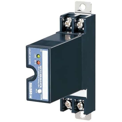
MDW5ALW LIGHTNING SURGE PROTECTOR FOR LonWorks


Tình trạng: In stock
Contact: 0989649965
Số lượt xem: 1138
Detail
·Some details are not shown. Please refer to specification sheets for all information.
MDW5ALW
Lightning Surge Protectors for
Electronics Equipment M-RESTER
LIGHTNING SURGE PROTECTOR FOR
LonWorks
(life monitor)
Functions & Features
• Designed specifically for the network
• Life monitor function helps you to decide when you should replace the surge protector
• LED and alarm contact output indicate the degradation and life span of the surge protection circuits
• Easy maintenance thanks to discharge elements installed on the element module
• No interruption of signal even unplugging head element
• DIN rail mounting
HEAD ELEMENT
MODEL: MDW5ALW–E
BASE
MODEL: MDW5ALW–B–[1]
ORDERING INFORMATION
Order the both pieces of this surge protector (the head element and the base), respectively required for the use. Order the pieces by separate only for replacement.
• Head element
Code number: MDW5ALW-E
• Base
Code number: MDW5ALW-B-[1]
Specify a code from below for [1].
(e.g. MDW5ALW-B-R)
[1] POWER INPUT
AC Power
M2: 100 – 240 V AC (Operational voltage range 90 – 264 V,
47 – 66 Hz)
DC Power
R: 24 V DC
(Operational voltage range 24 V ±10 %, ripple 10 %p-p max.)
P: 110 V DC
(Operational voltage range 85 – 150 V, ripple 10 %p-p max.)
APPLICABLE NETWORK
LonWorks FTT-10A network
This unit is not applicable to LonWorks Link Power network.
GENERAL SPECIFICATIONS
Construction: Plug-in
Degree of protection: IP20 (If the solderless terminals are covered with insulation tubes.)
Surge protection type: Two-port SPD
Connection
• Transmission, power & grounding: M3 screw terminals (torque 0.8 N·m)
• Alarm output: Euro Type Connector Terminal
(torque 0.6 N·m)
Applicable wire size
Line, communication: See the 'External Dimensions.'
Alarm output: 0.2 to 2.5 mm2, stripped length 7 mm
Screw terminal
• Transmission, power & grounding: Nickel-plated steel
• Alarm output: Tin-plated copper alloy
Housing material: Flame-resistant resin (black)
Indicators
• ALM: Green/Amber/Red tricolor LED
OFF when no surge is detected.
Green ON when surge is detected more than once.
Amber ON when element life is about to expire.
(Prepare to replace)
Red ON when element life is expired or deteriorated
or internal battery is drained. (Replace)
• PWR: Green LED
ON when power is supplyed.
OFF when the base power circuit is in error.
Degradation judged: When the leakage current at the voltage limiter exceeds approx. 100 μA
Life time judged: When the number of discharges of the discharge element reaches the expected life span.
Alarm contact: Relay N.C contact
• Element error: ON when life span of the discharge element has expired, the voltage limiter is degraded, battery drain or element is removed.
• Base error: ON with power circuit error or power supply failure
Rated load: 250 V AC @ 1 A (cos ø = 1)
30 V DC @ 1 A (resistive load)
Maximum switching voltage: 264 V AC or 125 V DC
Maximum switching power: 250 VA or 30 W
Minimum load: 5 V DC @ 10 mA
Battery: Lithium battery built in the element, used for life time judgement. No recharge or replacement available.
Battery life: ≥ 10 years
INSTALLATION
Power consumption
•AC: Approx. 2 VA at 100 V
Approx. 3 VA at 200 V
Approx. 4 VA at 240 V
•DC: ≤ 2 W
Operating temperature: -10 to +55°C (14 to 131°F)
Operating humidity: 30 to 90 %RH (non-condensing)
Mounting: DIN rail
Weight: 160 g (0.35 lb)
PERFORMANCE
Max. continuous operating voltage (Uc):
Line to line: ±1.5 V
Line to earth: ±100 V
SHLD to earth: ±160 V
Voltage protection level (Up):
@ 4 kV (1.2/50 μsec.)
Line to line: ±30 V
Line to earth: ±370 V
SHLD to earth: ±800 V
Response time:
Line to line: ≤ 4 nsec.
Line or SHLD to earth: ≤ 20 nsec.
Leakage current
(@ max. continuous operating voltage)
Line to line: ≤ 50 μA
Line to earth: ≤ 20 μA
SHLD to earth: ≤ 5 μA
Max. discharge current (Imax): 10 kA (8/20 μsec.), 1.0 kA (10/350 μsec.)
Nominal current (IN): 100 mA
Insulation resistance: ≥ 100 MΩ with 500 V DC
(surge protector circuit to alarm contact to power)
Dielectric strength: 2000 V AC @ 1 minute
(surge protector circuit to alarm contact to power)
Internal series resistance: ≤ 3.8 Ω (including return)
≤ 4.2 Ω (for only base, including return)
AC durability: 1 Arms (60 Hz 1 sec.) 5 times
Capacitance @ 1 MHz:
Line to line: Approx. 100 pF
Line to earth: Approx. 100 pF
SHLD to earth: Approx. 100 pF
Surge protection: IEC 61643-21 Categories C1, C2
EXTERNAL VIEW
EXTERNAL DIMENSIONS & TERMINAL ASSIGNMENTS unit: mm (inch)
SCHEMATIC CIRCUITRY & CONNECTION DIAGRAM
M-System Co., Ltd.
Products
-

MDCAT-NC LIGHTNING SURGE PROTECTOR FOR CC-Link IE Field Network
-

MDP-4R LIGHTNING SURGE PROTECTOR FOR RS-485 / RS-422
-

MDW5-4R LIGHTNING SURGE PROTECTOR FOR RS-485 / RS-422
-

MDCAT-A LIGHTNING SURGE PROTECTOR FOR ETHERNET
-

MDCAT LIGHTNING SURGE PROTECTOR FOR ETHERNET
-

MDM5E-A LIGHTNING SURGE PROTECTOR FOR ETHERNET
-

MD74R LIGHTNING SURGE PROTECTOR FOR RS-485 / RS-422
-

MDW5-CC LIGHTNING SURGE PROTECTOR FOR CC-Link
-
MD7FB LIGHTNING SURGE PROTECTOR FOR FOUNDATION Fieldbus
PRODUCTS LIST
- Signal Conditioners
- 2-wire Signal Conditioners
- Power Transducers
- Indicators
- Tower Lights
- Limit Alarms
- Gateway, Remote IO
- Paperless Recording System
- PC Recorder
- Web Data Loggers
- PID Control Components
- BA&Energy Monitoring Components
- Temperature Controllers
- Electric Actuators
- Lightning Surge Protectors
News Product
 IT40SW5F/6F, IT50SW5F/6F, IT60SW5F/6F Series")


STATISTIC
Visitor: 1056514Online: 14

