
")
MDP-PM LIGHTNING SURGE PROTECTOR FOR POTENTIOMETER USE


Tình trạng: In stock
Contact: 0989649965
Số lượt xem: 1078
Detail
·Some details are not shown. Please refer to specification sheets for all information.
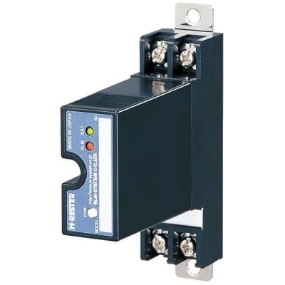
MDP-PM
Lightning Surge Protectors for
Electronics Equipment M-RESTER
LIGHTNING SURGE PROTECTOR FOR
POTENTIOMETER USE
Functions & Features
• Designed specifically for potentiometer or
slidewire circuits
• Protects potentiometer transmitters from lightning surge damage that enters on the wiring between the potentiometer and the transmitter
• Absorbs surges only without affecting instrumentation signal
• No interruption of signal by unplugging the protector element
MODEL: MDP–PM[1]
ORDERING INFORMATION
• Code number: MDP-PM[1]
Specify a code from below for [1].
(e.g. MDP-PM/A33/Q)
• Specify the specification for option code /Q
(e.g. /C01)
[1] OPTIONS (multiple selections)
DIN Rail Mounting Adapter
blank: Without
/A33: With adapter (model A-33)
Other Options
blank: none
/Q: Option other than the above (specify the specification)
SPECIFICATIONS OF OPTION: Q
COATING (For the detail, refer to M-System's web site.)
/C01: Silicone coating
/C02: Polyurethane coating
/C03: Rubber coating
GENERAL SPECIFICATIONS
Construction: Plug-in
Connection: M4 screw terminals (torque 0.8 N·m)
Screw terminal: Nickel-plated steel
Housing material: Flame-resistant resin (black)
INSTALLATION
Operating temperature: -5 to +55°C (23 to 131°F)
Operating humidity: 30 to 90 %RH (non-condensing)
Mounting: Surface or DIN rail
Weight: 140 g (0.31 lb), standard
165 g (0.36 lb), with DIN rail mounting adapter
PERFORMANCE
Max. continuous operating voltage (Uc):
B to C: ±7.5 V
B or C to A: 7.5 V
Line to earth: ±140 V
Voltage protection level (Up):
• @ 1 kV (100 A)
2 to 3: ±16 V
2 or 3 to 1: 16 V
Line to earth: ±650 V
• @ 2 kV (1 kA)
2 to 3: ±25 V
2 or 3 to 1: 25 V
Line to earth: ±800 V
Response time: ≤ 0.1 μsec.
Leakage current:
B to C: ≤ 10 μA @ ±7.5 V DC
B or C to A: ≤ 10 μA @ 7.5 V DC
Line to earth: ≤ 10 μA @ ±140 V DC
Max. discharge current (Imax): 5000 A (8 / 20 μs)
Nominal current (IN): 100 mA
Internal series resistance: 10 Ω ±0.1 %, 30 ppm/°C (17 ppm/°F)
Capacitance @ 1 MHz:
Line to line: ≤ 2000 pF
Line to earth: ≤ 100 pF
Surge protection: IEC 61643-21 Categories C1, C2, D1
CONNECTION EXAMPLES
GROUNDING
EXTERNAL DIMENSIONS & TERMINAL ASSIGNMENTS unit: mm (inch)
MOUNTING REQUIREMENTS unit: mm (inch)
SCHEMATIC CIRCUITRY & CONNECTION DIAGRAM
M-System Co., Ltd.
Products
-

MD-LC2 LIGHTNING SURGE PROTECTOR FOR STRAIN GAUGE USE
-
MDP-TC LIGHTNING SURGE PROTECTOR FOR THERMOCOUPLE USE
-

MD7RB LIGHTNING SURGE PROTECTOR FOR RTD USE
-

MDP-RB LIGHTNING SURGE PROTECTOR FOR RTD USE
-

MD7PM LIGHTNING SURGE PROTECTOR FOR POTENTIOMETER USE
-

MDK-LV LIGHTNING SURGE PROTECTOR FOR SIGNAL LINE WITH EXITATION USE
-

MD7LC LIGHTNING SURGE PROTECTOR FOR STRAIN GAUGE
-

MD7TC LIGHTNING SURGE PROTECTOR FOR THERMOCOUPLE USE
-

MDK-LC LIGHTNING SURGE PROTECTOR FOR STRAIN GAUGE USE
PRODUCTS LIST
- Signal Conditioners
- 2-wire Signal Conditioners
- Power Transducers
- Indicators
- Tower Lights
- Limit Alarms
- Gateway, Remote IO
- Paperless Recording System
- PC Recorder
- Web Data Loggers
- PID Control Components
- BA&Energy Monitoring Components
- Temperature Controllers
- Electric Actuators
- Lightning Surge Protectors
News Product
 IT40SW5F/6F, IT50SW5F/6F, IT60SW5F/6F Series")


STATISTIC
Visitor: 1045400Online: 3

