
")
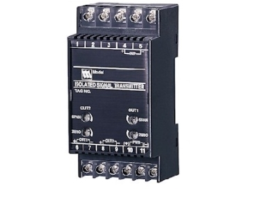
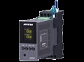
M5MS POTENTIOMETER TRANSMITTER


Tình trạng: In stock
Contact: 0989649965
M5MS POTENTIOMETER TRANSMITTER Potentiometer 100-10k ohms 100-240 Vac or 24 Vdc powered (CE for 24 Vdc type) Fast response 25 msec. optional
Số lượt xem: 1523
Detail
Products
-
W5MS POTENTIOMETER TRANSMITTER
W5MS POTENTIOMETER TRANSMITTER Potentiometer 100-10k ohms Independent output ranges selectable 100-240 Vac or 24 Vdc powered (CE for 24 Vdc type) Fast response 25 msec. optional
-

W2MS POTENTIOMETER TRANSMITTER
W2MS POTENTIOMETER TRANSMITTER Potentiometer 100-10k ohms Independent current/voltage output ranges can be specified. 100-240 Vac or 24 Vdc powered Fast response 25 msec. optional UL/cUL Class I, Div. 2 approva
-

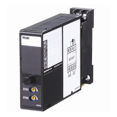
M3SMS POTENTIOMETER TRANSMITTER
M3SMS POTENTIOMETER TRANSMITTER Potentiometer 100-10k ohms 100-240 Vac / 24 Vdc universal power input Fast response 25 msec. optional
-
M2MS POTENTIOMETER TRANSMITTER
M2MS POTENTIOMETER TRANSMITTER Potentiometer 100-10k ohms 100-240 Vac or 24 Vdc powered Fast response 25 msec. optional UL/cUL Class I, Div. 2 approval
-
M3SXM POTENTIOMETER TRANSMITTER
M3SXM POTENTIOMETER TRANSMITTER Potentiometer 100-5k ohms Output selectable within 0-20 mA and ±10 V 24 Vdc powered
-
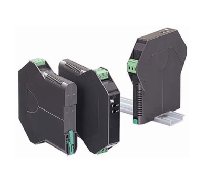
M3LM POTENTIOMETER TRANSMITTER
M3LM POTENTIOMETER TRANSMITTER Potentiometer 90-20k ohms Output selectable within 0-20 mA and ±10 V 10-32 Vdc powered DIP switch or PC configuration 125-point linearization using the PC Configurator
-

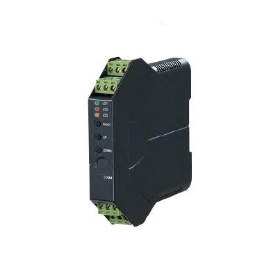
W2XM POTENTIOMETER TRANSMITTER
W2XM POTENTIOMETER TRANSMITTER Potentiometer 75-10k ohms Output selectable within 0-20 mA and ±10 V Independent current/voltage output ranges can be specified. 100-240 Vac or 24 Vdc powered
-
M2EXM POTENTIOMETER TRANSMITTER
M2EXM POTENTIOMETER TRANSMITTER Potentiometer 100-10k ohms Output selectable within 0-20 mA, ±5 V, and±10 V 100-240 Vac or 24, 110 Vdc powered
-

M2XM2 POTENTIOMETER TRANSMITTER
M2XM2 POTENTIOMETER TRANSMITTER Potentiometer 100-10k ohms Output selectable within 0-20 mA and ±10 V 100-240 Vac or 24 Vdc powered UL/cUL Class I, Div. 2 approval
PRODUCTS LIST
- Signal Conditioners
- 2-wire Signal Conditioners
- Power Transducers
- Indicators
- Tower Lights
- Limit Alarms
- Gateway, Remote IO
- Paperless Recording System
- PC Recorder
- Web Data Loggers
- PID Control Components
- BA&Energy Monitoring Components
- Temperature Controllers
- Electric Actuators
- Lightning Surge Protectors
News Product
 IT40SW5F/6F, IT50SW5F/6F, IT60SW5F/6F Series")


STATISTIC
Visitor: 1062432Online: 34

