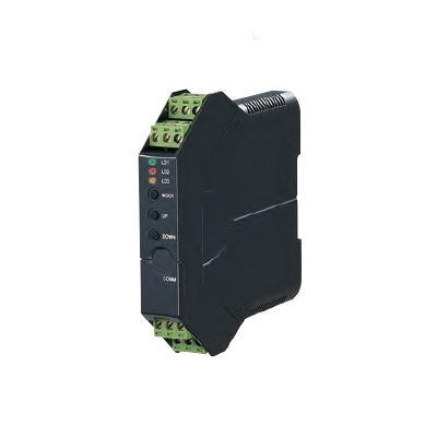
M2XM2
POTENTIOMETER TRANSMITTER
(PC programmable)
Functions & Features• Provides a DC output proportional to a potentiometer or slidewire position input
• PC programmable
• Potentiometer’s zero/span points can be captured by on-site calibrations
Typical Applications• Tank levels
• Positions: Compensating non-linear signal from the linking mechanism of a position detector
MODEL: M2XM2–1[1]–[2][3]
ORDERING INFORMATION
• Code number: M2XM2-1[1]-[2][3]
Specify a code from below for each [1] through [3].
(e.g. M2XM2-1Z1-R/CE/Q)
• Input range (e.g. 0 – 500 Ω)
• Output range (e.g. 4 – 20 mA DC)
• Specify the specification for option code /Q
(e.g. /C01/S01/SET)
INPUT POTENTIOMETER
1: Total resistance 100 Ω – 10 kΩ
(Configurator software is used to change input range
(total resistance).)
[1] OUTPUT
Current
Z1: Range 0 – 20 mA DC
Voltage
V1: Range -2.5 – +2.5 V DC
V2: Range -10 – +10 V DC
(Configurator
software is used to change output over the described range of the
selected suffix code. For changing out of this range, set the Output
Range Selectors inside the unit before software adjustment.)
[2] POWER INPUT
AC Power
M2: 100 – 240 V AC (Operational voltage range 85 – 264 V,
47 – 66 Hz)
(90 – 264 V for UL)
DC Power
R: 24 V DC
(Operational voltage range 24 V ±10 %, ripple 10 %p-p max.)
P: 110 V DC
(Operational voltage range 85 – 150 V, ripple 10 %p-p max.)
(110 V ±10 % for UL)
[3] OPTIONS (multiple selections)
Standards & Approvals (must be specified)
/N: Without CE or UL
/CE: CE marking
/UL: UL approval, CE marking
Other Options
blank: none
/Q: Option other than the above (specify the specification)
SPECIFICATIONS OF OPTION: Q (multiple selections)
COATING (For the detail, refer to M-System's web site.)
/C01: Silicone coating
/C02: Polyurethane coating
/C03: Rubber coating (UL not available)
TERMINAL SCREW MATERIAL
/S01: Stainless steel (UL not available)
EX-FACTORY SETTING
/SET: Preset according to the Ordering Information Sheet
(No. ESU-5093)
RELATED PRODUCTS
• PC configurator software (model: JXCON)
Downloadable at M-System’s web site.
A
dedicated cable is required to connect the module to the PC. Please
refer to the internet software download site or the users manual for the
PC configurator for applicable cable types.
GENERAL SPECIFICATIONS
Construction: Plug-in
Connection: M3 screw terminals (torque 0.8 N·m)
Screw terminal: Chromated steel (standard) or stainless steel
Housing material: Flame-resistant resin (black)
Isolation: Input to output to power
Overrange output: Approx. -15 to +115 %
(Negative current output is not provided.)
Manual zero adjustments: -5 to +5 %
(factory setting: 0 %)
Manual span adjustments: 95 to 105 %
(factory setting: 100 %)
Programming:
Downloaded from PC; linearization (100 points), input range (total
resistance), output range, zero and span, simulating output, etc.
Burnout: Upscale standard; downscale or no burnout optional by programming
Status indicator LED: Blinking patterns indicate different operating status of the transmitter.
Configurator connection: 2.5 dia. miniature jack;
RS-232-C level
INPUT SPECIFICATIONS
•
Potentiometer: 100 Ω – 10 kΩ
Range : Minimum span0 – 100 Ω : 2.5 Ω
0 – 300 Ω : 3.0 Ω
0 – 1000 Ω : 10 Ω
0 – 10 kΩ : 10 Ω
Excitation: ≤ 0.5 V DC at 1000 Ω
If not specified, default value is 1000 Ω.
OUTPUT SPECIFICATIONS
■ DC CurrentOperational range: 0 – 24 mA DC
Output range: 0 – 20 mA DC
Minimum span: 1 mA
Offset: Lower range can be any specific value within the output range provided that the minimum span is maintained.
Load resistance: Output drive 15 V max.
(e.g. 4 – 20 mA: 750 Ω [15 V ÷ 20 mA])
If not specified, the output range is 4 – 20 mA DC.
■
DC Voltage
Code V1 (narrow spans)
Operational range: -3 – +3 V DC
Output range: -2.5 – +2.5 V DC
Minimum span: 250 mV
Code V2 (wide spans)Operational range: -11.5 – +11.5 V DC
Output range: -10 – +10 V DC
Minimum span: 1 V
Offset: Lower range can be any specific value within the output range provided that the minimum span is maintained.
Load resistance: Output drive 1 mA max.
(e.g. 1 – 5 V: 5000 Ω [5 V ÷ 1 mA])
If not specified, the output range is shown below.
V1: 0 – 1 V DC
V2: 1 – 5 V DC
INSTALLATION
Power Consumption
•
AC:
Approx. 3 VA at 100 V
Approx. 4 VA at 200 V
Approx. 5 VA at 264 V
•
DC: Approx. 2 W
Operating temperature: -30 to +60°C (-22 to +140°F)
Operating humidity: 30 to 90 %RH (non-condensing)
Mounting: Surface or DIN rail
Weight: 120 g (0.26 lb)
PERFORMANCE in percentage of span
Accuracy: Input accuracy + output accuracy
Inversely proportional to the span.
Input accuracy: (% of max. input range)
(Range)
0 – 100 Ω : ±0.02 %
0 – 300 Ω : ±0.02 %
0 – 1000 Ω : ±0.01 %
0 – 10 kΩ : ±0.02 %
Output accuracy: ±0.04 % of max. output range
Temp. coefficient: ±0.015 %/°C (±0.008 %/°F) of max. span at -5 to +55°C [23 to 131°F]
Response time: ≤ 0.9 sec. (0 – 90 %)
Burnout response time: ≤ 30 sec.
Line voltage effect: ±0.1 % over voltage range
Insulation resistance: ≥ 100 MΩ with 500 V DC
Dielectric strength: 2000 V AC @1 minute (input to output to power to ground)
CALCULATION EXAMPLES OF OVERALL ACCURACY
[Example] Input Type 0 – 1000 Ω, Input Range 250 – 750 Ω ,Output Type 0 – 20 mA, Output Range 4 – 20 mA
Max. Input Range (1000 Ω) ÷ Span (500 Ω) × 0.01 %
= 0.02 %
Max. Output Range (20 mA) ÷ Span (16 mA) × 0.04 %
= 0.05 %
Overall accuracy = 0.02 % + 0.05 % = ±0.07 %
STANDARDS & APPROVALS
EU conformity:
EMC Directive
EMI EN 61000-6-4
EMS EN 61000-6-2
Low Voltage Directive
EN 61010-1
Installation Category II
Pollution Degree 2
Input or output to power: Reinforced insulation (300 V)
Input to output: Basic insulation (300 V)
RoHS Directive
EN 50581
Approval:
UL/C-UL nonincendive Class I, Division 2,
Groups A, B, C, and D
(ANSI/ISA-12.12.01, CAN/CSA-C22.2 No.213)
UL/C-UL general safety requirements
(UL 61010-1, CAN/CSA-C22.2 No.61010-1)
EXTERNAL VIEW
Refer to the instruction manual for detailed procedures.
EXTERNAL DIMENSIONS & TERMINAL ASSIGNMENTS unit: mm (inch)
SCHEMATIC CIRCUITRY & CONNECTION DIAGRAM
M-System Việt Nam
Email: Sales@m-system.com.vn

")


 IT40SW5F/6F, IT50SW5F/6F, IT60SW5F/6F Series")


