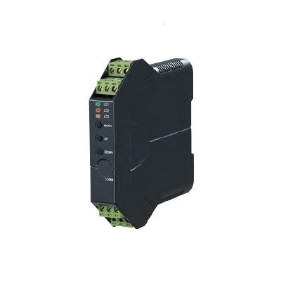
(2 channels, PC programmable)
Functions & Features
• Potentiometer’s zero/span points can be captured by on-site calibrations
• 2 channels
• Adjustments with the front button
• OEL display with good visibility
• Linearization available for each channel (111 points)
Typical Applications• Tank levels
• Positions: Compensating non-linear signal from the linking mechanism of a position detector
MODEL: M1EXM-2–[1][2]
ORDERING INFORMATION
• Code number: M1EXM-2-[1][2]
Specify a code from below for each of [1] and [2].
(e.g. M1EXM-2-M2/Q)
• Specify the specification for option code /Q
(e.g. /C01/SET)
NO. OF CHANNELS
2: 2 channels
INPUT
Total resistance 100 Ω – 10 kΩ
OUTPUT – Field-selectable
◆ DC Output
• Current output: 0 - 20 mA DC
• Voltage output: -5 - +5 V DC
• Voltage output: -10 - +10 V DC
[1] POWER INPUT
AC Power
M2: 100 – 240 V AC (Operational voltage range 85 – 264 V,
47 – 66 Hz)
DC Power
R: 24 V DC
(Operational voltage range 24 V ±10 %, ripple 10 %p-p max.)
P: 110 V DC
(Operational voltage range 85 – 150 V, ripple 10 %p-p max.)
[2] OPTIONS
blank: none
/Q: With options (specify the specification)
SPECIFICATIONS OF OPTION: Q (multiple selections)
COATING (For the detail, refer to M-System's web site.)
/C01: Silicone coating
/C02: Polyurethane coating
/C03: Rubber coating
EX-FACTORY SETTING
/SET: Preset according to the Ordering Information Sheet
(No. ESU-5983)
RELATED PRODUCTS
• Installation base (model: M1E-BS2)
• M1E configurator software (model: M1ECFG)
Downloadable at M-System’s web site.
A
dedicated cable is required to connect the module to the PC. Please
refer to the internet software download site or the users manual
(EM-5981) for the M1E configurator for applicable cable types.
GENERAL SPECIFICATIONS
Construction: Plug-in
Connection• Connected to base with connector
• Base
M2.6 screw terminals (torque: 0.5 N·m)
Applicable solderless terminal size (M3)
Screw terminal: Nickel-plated steel
Housing material: Flame-resistant resin (black)
Isolation: Ch1.input to ch2.input to Ch1.output to ch2.output to power
Overrange output: Approx. -5 to +105 % (Not available for current output not greater than 0 mA)
Output zero fine adj. range: -5 to +5% (front button)
Output span fine adj. range: 95 to 105% (front button)
Configuration: Program with front buttons or Via PC.
Programmable features include: Refer to the parameter list.
Configurator connection: 2.5 dia. miniature jack;
RS-232-C level
DISPLAY
Display functions: Displays and sets measured range, engineering unit
Display size: Approx. 15.6 × 20.8 mm (0.61” × 0.82”)
Number of pixels: 68 × 95 (horizontal × vertical)
Character color: Yellow
Display life: Approx. 50000 hours
(Expected
time for the Display brightness to be reduced to 50 % when the Display
is used continuously with brightness setting 2 in 25 ℃)
Display type: OEL display
Display digit: Negative 5 digits, positive 6 digits (-99999 to 999999)
Decimal point position: Selectable
INPUT SPECIFICATIONS
Minimum span: 5 % of total resistance
Excitation: Approx. 0.5 V DC
OUTPUT SPECIFICATIONS
■ DC Current
Output range: 0 – 20 mA DC
Conformance range: 0 – 21mA DC
Minimum span: 1 mA
Load resistance: Output drive 15 V max.
(e.g. 4 – 20 mA: 750 Ω [15 V ÷ 20 mA])
(Not available to output less than 0 mA, output range may not be extended to -5 %)
■
DC Voltage
Output range: -5 - +5 V DC, -10 - +10 V DC
Conformance range: -5.5 - +5.5 V DC, -11 - +11 V DC
Minimum span: 250 mV, 1 V
Load resistance: 200 kΩ min.
INSTALLATION
Power Consumption
•
AC:
≤ 7 VA at 100 V
≤ 10 VA at 200 V
≤ 12 VA at 264 V
•
DC: ≤ 4 W
Operating temperature: -5 to +55°C (23 to 131°F)
Storage temperature: -5 to +55°C (23 to 131°F)
Operating humidity: 10 to 85 %RH (non-condensing)
Mounting: Surface or DIN rail
Weight: 120 g (0.26 lb) except base
PERFORMANCE
Accuracy: Input accuracy + output accuracy
input accuracy + (output accuracy × segment gain) when segment gain > 1
See CALCULATION EXAMPLES OF OVERALL ACCURACY.
Inversely proportional to the setting span.
Input accuracy (% of max. input range): ±1Ω or ±0.03 %, whichever is greater.
Display accuracy:
Input display: Input accuracy ±1 digit
Output display: Input accuracy + output accuracy ±1 digit
Output accuracy: (% of max. output range)
0 - 20 mA: ±0.06 %
-5 - +5 V: ±0.03 %
-10 - +10 V: ±0.03 %
Temp. coefficient (% of max. I/O range): ±0.015 %/°C (±0.008 %/°F)
Response time (filter time constant: 0 sec.): ≤ 0.5 sec.
(0 – 90 %)
Line voltage effect: ±0.1 % over voltage range
Insulation resistance: ≥ 100 MΩ with 500 V DC
Dielectric strength: 1500 V AC @ 1 minute
(Ch1 input to Ch2 input to Ch1 output to Ch2 output to power to ground)
CALCULATION EXAMPLES OF OVERALL ACCURACY
[Example] Total Resistance 1000 Ω, Input Setting 100 – 600 Ω, Output Range 0 – 20 mA, Output Setting 4 – 20 mA, Segment Gain 1.5
■
Overall accuracy• Input Accuracy = Total Resistance (1000 Ω) ÷ Input Span Setting (500 Ω) × 0.03 % = 0.06 %
Less than 1 Ω thus 1 Ω (0.1%) is selected.
• Output Accuracy = Output Range Span (20 mA) ÷ Output Span Setting (16 mA) × 0.06 % × Segment Gain (1.5) = 0.1125 %
Overall Accuracy = 0.1 + 0.1125 = ±0.2125 %
STANDARDS & APPROVALS
EU conformity:
EMC Directive
EMI EN 61000-6-4
EMS EN 61000-6-2
Low Voltage Directive
EN 61010-1
Installation Category II
Pollution Degree 2
Input or output to power: Reinforced insulation (300 V)
RoHS Directive
EN 50581
EXTERNAL VIEW
Refer to the operating manual (EM-5983-B) for detailed procedures.
TERMINAL ASSIGNMENTS
PARAMETER LIST
EXTERNAL DIMENSIONS & TERMINAL ASSIGNMENTS unit: mm (inch)
MOUNTING REQUIREMENTS unit: mm (inch)
SCHEMATIC CIRCUITRY & CONNECTION DIAGRAM
M-System Việt Nam
Email: Sales@m-system.com.vn

")


 IT40SW5F/6F, IT50SW5F/6F, IT60SW5F/6F Series")


