
")
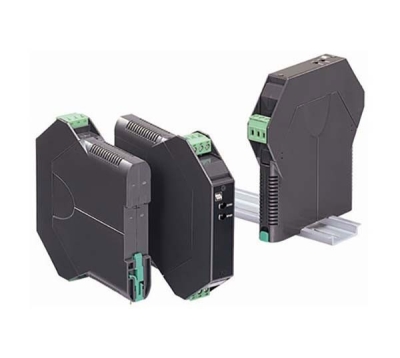
B6U-B 2-WIRE UNIVERSAL TEMPERATURE TRANSMITTER


Tình trạng: In stock
Contact: 0989649965
B6U-B 2-WIRE UNIVERSAL TEMPERATURE TRANSMITTER DC mV, V & mA, T/C, RTD, Pot and resistance input 12-42 Vdc powered (max. 28 V approved) NEMA 4X, IP66/IP67 enclosure ATEX Zone 0 approval FM Class I, II, III, Div. 1 & Class I, II, Div. 2 approval
Số lượt xem: 2095
Detail
Products
-

B3PU PROFIBUS temperature transmitter
B3PU PROFIBUS temperature transmitter mV, V, T/C, RTD, resistance and potentiometer input 9-30 Vdc powered
-

B3HU2 2-WIRE UNIVERSAL TEMPERATURE TRANSMITTER
B3HU2 2-WIRE UNIVERSAL TEMPERATURE TRANSMITTER Voltage, T/C, RTD and resistance input 9-35 Vdc powered HART version: 7
B3HU2 2-WIRE UNIVERSAL TEMPERATURE TRANSMITTER
-
B3HU-1/A 2-WIRE UNIVERSAL TEMPERATURE TRANSMITTER
B3HU-1/A 2-WIRE UNIVERSAL TEMPERATURE TRANSMITTER mV, V, T/C, RTD, resistance and potentiometer input 12-42 Vdc powered (max. 28 V approved) ATEX Zone 0 approval
-
27HU 2-WIRE UNIVERSAL TEMPERATURE TRANSMITTER
27HU 2-WIRE UNIVERSAL TEMPERATURE TRANSMITTER DC mV, V & mA, T/C, RTD and resistance input 8-35 Vdc powered (max. 28 V approved) ATEX Zone 0 approval FM Class I, Div. 1 & Zone 0 approval
PRODUCTS LIST
- Signal Conditioners
- 2-wire Signal Conditioners
- Power Transducers
- Indicators
- Tower Lights
- Limit Alarms
- Gateway, Remote IO
- Paperless Recording System
- PC Recorder
- Web Data Loggers
- PID Control Components
- BA&Energy Monitoring Components
- Temperature Controllers
- Electric Actuators
- Lightning Surge Protectors
News Product
 IT40SW5F/6F, IT50SW5F/6F, IT60SW5F/6F Series")


STATISTIC
Visitor: 1053960Online: 20

