
")
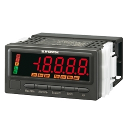
47DR RTD INPUT DIGITAL PANEL METER


Tình trạng: In stock
Contact: 0989649965
Digital Panel Meters 47 Series RTD INPUT DIGITAL PANEL METER (5 digit, LCD display type)
Số lượt xem: 1196
Detail
47DR
Digital Panel Meters 47 Series
RTD INPUT DIGITAL PANEL METER
(5 digit, LCD display type)
Functions & Features
• 5 digit RTD input digital panel meter
• 1/8 DIN size
• Display color can be changed at alarm
• Bargraph indicator shows approximate measuring status
• 12 V or 24 V excitation supply
• External event trigger input
• RS-485 / Modbus RTU output
• Infrared interface
• BCD output
• Loop test output (DC output option)
• IP66 front panel
• Separable terminal block
• Safety terminal cover tethered to the device with a strap
MODEL: 47DR-1[1][2][3]-[4][5]
ORDERING INFORMATION
• Code number: 47DR-1[1][2][3]-[4][5]
Specify a code from below for each [1] through [5].
(e.g. 47DR-1111-M2/Q)
• Specify the specification for option code /Q
(e.g. /C01/S01/SET)
INPUT – Field-selectable
RTD
1: JPt 100 (JIS ’89)
Pt 100 (JIS ’89)
Pt 100 (JIS ’97, IEC)
Pt 50Ω (JIS ’81)
Pt 1000
[1] DC OUTPUT
0: Without
1: With
[2] EXCITATION SUPPLY
1: +12 V sensor excitation
2: +24 V two-wire transmitter excitation
[3] I/O OPTIONS
0: None
1: Alarm output: N.O. relay, 4 points
2: Alarm output: SPDT relay, 2 points
3: Alarm output: N.O. photo MOSFET relay, 4 points
4: Network interface: RS-485 / Modbus RTU
5: BCD output
6: Event trigger input
7: Alarm output: N.O. relay, 4 points
+ Network interface: RS-485 / Modbus RTU
8: Alarm output: SPDT relay, 2 points +
Network interface: RS-485 / Modbus RTU
9: Alarm output: N.O. photo MOSFET relay, 4 points + BCD output
A: Event trigger input + BCD output
[4] POWER INPUT
AC Power
M2: 100 – 240 V AC (Operational voltage range 85 – 264 V, 50/60 Hz)
DC Power
R: 24 V DC
(Operational voltage range 24 V ±10 %, ripple 10 %p-p max.)
P: 110 V DC
(Operational voltage range 85 – 150 V, ripple 10 %p-p max.)
[5] OPTIONS
blank: none
/Q: With options (specify the specification)
SPECIFICATIONS OF OPTION: Q (multiple selections)
COATING (For the detail, refer to M-System's web site.)
Moving parts and indicators are not coated.
/C01: Silicone coating
/C02: Polyurethane coating
/C03: Rubber coating
TERMINAL SCREW MATERIAL
/S01: Stainless steel
EX-FACTORY SETTING
/SET: Preset according to the Ordering Information Sheet
(No. ESU-9509)
RELATED PRODUCTS
• Connector terminal block (model: CNT)
• Special cable (model: HDR40)
• Infrared Communication Adaptor (model: COP-IRU)
• PC configurator software (model: 47DCFG)
Downloadable at M-System’s web site.
GENERAL SPECIFICATIONS
Construction: Panel flush mounting
Degree of protection: IP66; applicable to the front of the panel meter mounted according to the specified panel cutout
Connection
Input, excitation supply, DC output, relay output,
network interface, power: M3 separable screw terminal
(torque 0.6 N·m)
Photo MOSFET relay, event trigger input: Euro Type
Connector Terminal
(applicable wire size: max. 1.3 dia., 0.5 – 1.25 mm2,
stripped length 7 - 8 mm)
BCD output: 50-pin connector
(Honda Tsushin Kogyo HDR-EC50LFDT1-SLE+)
Screw terminal: Nickel-plated steel (standard) or stainless steel
Housing material: Flame-resistant resin (gray)
Isolation: Input or excitation supply to DC output to
HH output or H output to L output or LL output to network or BCD output or event trigger input to power
Burnout: Upscale standard; downscale optional by programming
Linearization: Standard
Infrared communication: Transmission distance max. 1 meter (for use with the COP-IRU)
Setting: (Front button)
• Input type
• Alarm setpoint
• Hysteresis (deadband)
• Averaging
• Burnout
• Others
(Refer to the instruction manual for details)
Sampling rate: 20 times/sec. (50 msec.)
Averaging: Simple average, moving average or no averaging
Lockout setting: Prohibiting certain operations; protecting settings
DISPLAY
Main display: 5 digits (6 digits when parameter is setting), LCD with LED backlight, 7-segment, 14.2 mm (.56) high
Color: Red or green changeable at alarm
Display range: -20000 to 99999
Decimal point position: 2 decimal places, 1 decimal place or none
Zero indication: Higher-digit zeros are suppressed.
Sub display: 7 digits, LCD with LED backlight, 7-segment,
5.5 mm (.22) high
Color: Green
Over-range indication: ‘S.ERR’ (main display) and ‘UNDER’ or ‘OVER’ (sub display) blinking when the input signal is out of the usable range.
Burnout indication: ‘B.ERR’ blinking
Bargraph
No. of LED segments: 20, displayed with divided by 10
Color: Amber
Alarm status indication
All setpoints can be set and indicated regardless of alarm output options. Each is independently set either for Hi or Lo alarm trip.
LL indicator: Turns on in red when the LL alarm is tripped.
L indicator: Turns on in red when the L alarm is tripped.
H indicator: Turns on in green when the H alarm is tripped.
HH indicator: Turns on in green when the HH alarm is tripped.
P indicator: Turns on in amber when none of the other alarms is tripped.
Status indicators: Max, Min
Display max./min. value, Amber LED turns on
Function indicators
Hld: Turns on in green when HOLD signal is ON
TG: Turns on in green when TIMING signal is ON
NG: Turns on in green when a parameter is invalid
Ini: Unused
Alm: Unused
°F: Turns on in green when temperature unit is set to °F
℃ : Turns on in green when temperature unit is set to ℃
Engineering unit indication: Sticker label attached
DC, AC, mV, V, kV, μA, mA, A, kA, mW, W,
kW, var, kvar, Mvar, VA, Hz, Ω, kΩ, MΩ,
cm, mm, m, m/sec, mm/min, cm/min, m/min,
m/h, m/s2, inch, ℓ, ℓ/s, ℓ/min, ℓ/h, m3, m3/sec,
m3/min, m3/h, Nm3/h, N·m, N/m2, g, kg, kg/h,
N, kN, Pa, kPa, MPa, t, t/h, ℃, °F, %RH, J,
kJ, MJ, rpm, sec, min, min-1, pH, %, ppm, etc.
EXCITATION SUPPLY
■ +12V SENSOR EXCITATION
Output voltage (across the terminals 5 – 6): 12 – 16 V DC with no load
10.8 V DC minimum at 80 mA
Current rating: 84 mA DC maximum
• Shortcircuit Protection
Current limited: 97 mA maximum
Protected time duration: No limit
■ +24V TWO-WIRE TRANSMITTER EXCITATION
Output voltage (across the terminals 5 – 6): 24 – 28 V DC with no load
22 V DC minimum at 20 mA
Current rating: ≤ 22 mA DC
• Shortcircuit Protection
Current limited: 30 mA max.
Protected time duration: No limit
INPUT SPECIFICATIONS
■ RTD: 3-wire RTDs
Maximum leadwire resistance: 20 Ω per wire
Sensing current: 1mA (JPt 100, Pt 100), 2mA (Pt 50Ω), 0.1mA (Pt 1000)
DC OUTPUT SIGNAL SPECIFICATIONS
I/O OPTIONS
■ Event Trigger Input: Dry contact or NPN open collector
Input current: ≤ 3 mA
Sensing: 6 V
Contact detecting: ≤ 1.5 V at ON; ≥ 3 V at OFF
Signal ID and Details
S_TMR: Startup Timer
Measuring starts in the predetermined time after
detecting the signal turning on.
TIMING: Timing
Used for various timing hold functions
ZERO: Forced Zero
Not used
HOLD: Hold data
Reading measured signal stops and the last value is held
when HOLD signal is turned on.
RESET: Reset data
The device is reset when RESET signal is
turned on.
■ Alarm Output: Relay contact
Rated load: 250 V AC @ 3 A (cos ø = 1)
30 V DC @ 3 A (resistive load)
Maximum switching voltage: 250 V AC, 30 V DC
Maximum switching power: 750 VA, 90 W (resistive load)
Minimum load: 5 V DC @ 10 mA
Mechanical life: ≥ 5 × 10⁶ cycles (rate 180 cycles/min.)
■ Alarm Output: Photo MOSFET relay
Rated load: 120 V AC/DC @ 80 mA (resistive load)
ON resistance: 25 Ω
Permissible loss: 250 mW
■ Network Interface
Transmission: Half-duplex, asynchronous, no procedure
Interface: Conforms to TIA/EIA-485-A
Max. transmission distance: 500 meters
Baud rate: 1.2 – 38.4 kbps
Max. number of nodes: 31 (except the master)
Protocol: Modbus RTU
Parity: None, odd or even
Stop bit: 1 bit, 2 bits
Node address: 1 to 247
Media: Shielded twisted-pair cable (CPEV-S 0.9 dia.)
Terminating resistor: Built-in (Connect across T2 - T3, when the unit is the end of the line)
■ BCD Output + Control Signals
• Input Signals: Dry contact or NPN open collector
Input current: ≤ 3 mA
Sensing: 6 V
Contact detecting: ≤ 1.5 V at ON; ≥ 3 V at OFF
Signal ID and Details
REQ: Request BCD data
Valid data in approx. 30 msec. after detecting
the signal’s rising edge
MIN_REQ: Request Minimum reading data
Valid data in approx. 30 msec. after detecting
the signal’s rising edge
MAX_REQ: Request Maximum reading data
Valid data in approx. 30 msec. after detecting
the signal’s rising edge
HOLD: Hold data
Reading measured signal stops and the last value is
held when HOLD signal is turned on.
RESET: Reset data
All BCD data turn off when RESET signal is
turned on.
• Output Signals: NPN open collector
Max. load voltage: 24 V DC
Max. load current: 10 mA
Saturation voltage: ≤ 0.3 V DC
Leakage current: ≤ 500 μA
Signal ID and Details
DATA (Do 11...Do 68): BCD output data in 6 digits
Do 1x = LSD ... Do 6x = 6th LSD
POL: BCD Polarity
ON = (–), OFF = (+)
OVF: BCD Overflow/underflow
Output given at overflow or underflow
DAV: Data Valid
ON = valid, OFF = invalid
RUN: Run
Means the meter is functioning.
ON = Measuring or testing mode
OFF = Error except overflow/underflow
No DAV or DATA output is given when
RUN signal is not provided.
• Alarm Output Signals: NPN open collector
Max. load voltage: 24 V DC
Max. load current: 50 mA
Saturation voltage: ≤ 1.1 V
Leakage current: ≤ 500 μA
Signal ID and Details
HH: HH alarm trip output
H: H alarm trip output
PASS: PASS zone output
L: L alarm trip output
LL: LL alarm trip output
INSTALLATION
Power consumption
•AC: Max. 12 VA
•DC: 3.5 W max.
Operating temperature: -10 to +55°C (14 to 131°F)
Operating humidity: 30 to 90 %RH (non-condensing)
Mounting: Panel flush mounting
Weight: 300 g (0.66 lb)
PERFORMANCE in percentage of max. span
Accuracy
Display: ±0.5°C ±1 digit (±0.9°F ±1 digit)
Output: ±0.1% (DC output = display + output)
Temp. coefficient: ±0.015 %/°C (±0.008 %/°F)
Input resolution: Max. 19 bits
Output resolution: Max. 14 bits
Response time: ≤ 0.5 sec.
(alarm output: 0 – 100 % at 90 % setpoint)
≤ 0.5 sec. (DC output: 0 – 90 %)
Burnout response: ≤ 5 sec.
Line voltage effect: ±0.1 % over voltage range
Insulation resistance: ≥ 100 MΩ with 500 V DC
Dielectric strength: 2000 V AC @ 1 minute
(input or excitation supply to DC output to HH output or H output to L output or LL output to network or BCD output or event trigger input to power to ground)
EXTERNAL VIEW
COMMUNICATION CABLE CONNECTIONS
EXTERNAL DIMENSIONS & TERMINAL ASSIGNMENTS unit: mm (inch)
MOUNTING REQUIREMENTS unit: mm
SCHEMATIC CIRCUITRY & CONNECTION DIAGRAM
BCD OUTPUT TIMING CHART
Request signals (REQ, MAX_REQ, MIN_REQ) from an external device (e.g. PLC) are required in order to read out BCD data.
All signals in the following charts are in the negative logic (ON at LOW signal, as factory set).
VIEWING ANGLE
The display is designed to provide the optimal legibility when viewed from the angles as shown below.
SYSTEM CONFIGURATION EXAMPLES
M-System Co., Ltd.
Products
-

43AL1 LOOP POWERED DIGITAL PANEL METER
43AL1 Digital Panel Meters 43 Series
-

43DV2 DC INPUT DIGITAL PANEL METER
43DV2 Digital Panel Meters 43 Series
-

40LV DC INPUT DIGITAL PANEL METER
40LV Digital Panel Meters 40 Series
-
40DV DC INPUT DIGITAL PANEL METER
40DV Digital Panel Meters 40 Series
-

40DT THERMOCOUPLE INPUT DIGITAL PANEL METER
40DT Digital Panel Meters 40 Series
-

40DR RTD INPUT DIGITAL PANEL METER
40DR Digital Panel Meters 40 Series
-

40DPT AC VOLTAGE INPUT DIGITAL PANEL METER
40DPT Digital Panel Meters 40 Series
-

40DN LOOP POWERED DIGITAL PANEL METER
40DN Digital Panel Meters 40 Series
-

40DCT AC CURRENT INPUT DIGITAL PANEL METER
40DCT Digital Panel Meters 40 Series
PRODUCTS LIST
- Signal Conditioners
- 2-wire Signal Conditioners
- Power Transducers
- Indicators
- Tower Lights
- Limit Alarms
- Gateway, Remote IO
- Paperless Recording System
- PC Recorder
- Web Data Loggers
- PID Control Components
- BA&Energy Monitoring Components
- Temperature Controllers
- Electric Actuators
- Lightning Surge Protectors
News Product
 IT40SW5F/6F, IT50SW5F/6F, IT60SW5F/6F Series")


STATISTIC
Visitor: 1057109Online: 20

