
")
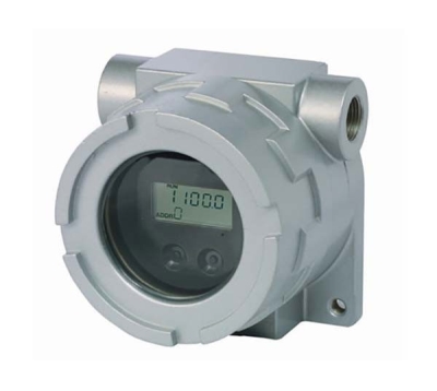
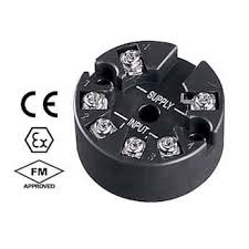
27RS RTD TRANSMITTER


Tình trạng: In stock
Contact: 0989649965
27RS RTD TRANSMITTER Pt100, Pt1000, Pt500 selectable Function monitor LED optional 9-35 Vdc powered ATEX Zone 0 approval FM Class I, Div. 1 & Zone 0 approval
Số lượt xem: 2050
Detail
Products
-

B5RS - RTD TRANSMITTER
B5RS - RTD TRANSMITTER Specify Pt100, Pt50, Ni508.4 and temp. range. Special RTD acceptable 12-28 Vdc powered Fast response 25 msec. optional
-
B5TS - THERMOCOUPLE TRANSMITTER
B5TS - THERMOCOUPLE TRANSMITTER Specify K, E, J, T, B, R, S, N and temp. range. Special T/C acceptable 12-28 Vdc powered Fast response 25 msec. optional
-

B3FR - RTD TRANSMITTER
B3FR - RTD TRANSMITTER Pt100, Ni120, Cu10 selectable 12-45 Vdc powered
-
B3FT-1 THERMOCOUPLE TRANSMITTER
B3FT-1 THERMOCOUPLE TRANSMITTER K, J, T or E, R, N selectable 12-45 Vdc powered
-
B6U 2-WIRE UNIVERSAL TEMPERATURE TRANSMITTER
B6U 2-WIRE UNIVERSAL TEMPERATURE TRANSMITTER DC mV, V & mA, T/C, RTD, Pot and resistance input 12-42 Vdc powered (max. 28 V approved) ATEX Zone 0 approval FM Class I, Div. 1 & 2 approval
-
26REX RTD TRANSMITTER
26REX RTD TRANSMITTER Pt100 input. Select temp. range. Non-isolated. 12-30 Vdc powered. ATEX Zone 0 approval
-

26R1 RTD TRANSMITTER
26R1 RTD TRANSMITTER Pt100 input. Select temp. range. Non-isolated. 8.5-32 Vdc powered Economical model
-

26TS1 THERMOCOUPLE TRANSMITTER
26TS1 THERMOCOUPLE TRANSMITTER Specify K, E, J, T, B, R, S, N and temp. range. Special T/C acceptable 12-32 Vdc powered Fast response 25 msec. optional
-
27R RTD TRANSMITTER
27R RTD TRANSMITTER Pt100, Pt1000, Pt500 selectable. Non-isolated. Function monitor LED optional 9-35 Vdc powered ATEX Zone 0 approval FM Class I, Div. 1 & Zone 0 approval
PRODUCTS LIST
- Signal Conditioners
- 2-wire Signal Conditioners
- Power Transducers
- Indicators
- Tower Lights
- Limit Alarms
- Gateway, Remote IO
- Paperless Recording System
- PC Recorder
- Web Data Loggers
- PID Control Components
- BA&Energy Monitoring Components
- Temperature Controllers
- Electric Actuators
- Lightning Surge Protectors
News Product
 IT40SW5F/6F, IT50SW5F/6F, IT60SW5F/6F Series")


STATISTIC
Visitor: 1045332Online: 3

