
")
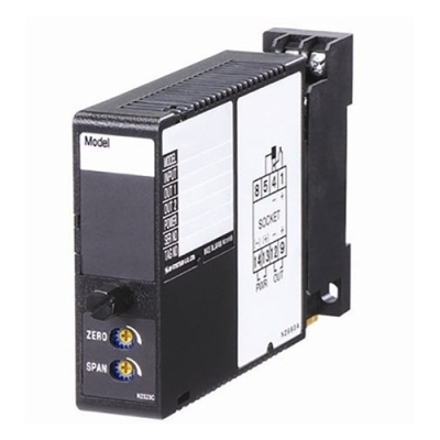
W5VS SIGNAL TRANSMITTER


Tình trạng: In stock
Contact: 0989649965
W5VS SIGNAL TRANSMITTER Specific input range within ±300 V; current input with a resistor. Independent output ranges selectable 85-264 Vac or 11-27, 24, 110 Vdc powered (CE for 24 Vdc type) Fast response 25 msec. optional
Số lượt xem: 1473
Detail
Products
-

W2DYS CURRENT LOOP SUPPLY
W2DYS CURRENT LOOP SUPPLY
-
M2VS SIGNAL TRANSMITTER
M2VS SIGNAL TRANSMITTER M-ystem VIệt Nam
M2VS SIGNAL TRANSMITTER M-ystem VIệt Nam
-

M2VT SIGNAL TRANSMITTER
M2VT SIGNAL TRANSMITTER Specific input range within ±300 V; current input with a resistor. 100-240 Vac or 11-27, 24, 110 Vdc powered Fast response 25 msec. optional Operating temperature: -20 to +80 °C (-4 to +176°F)
-
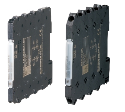
M60SYV ISOLATOR
M60SYV ISOLATOR Input/Output: 4-20 mA/4-20 mA, 4-20 mA/1-5 V, 1-5 V/4-20 mA, 1-5 V/1-5 V, ±10 V 24 Vdc powered Spring clamp connection for easy wiring 6-mm wide ultra-slim design
-

M6SYV ISOLATOR
M6SYV ISOLATOR Input/Output: 4-20 mA/4-20 mA, 4-20 mA/1-5 V, 1-5 V/4-20 mA, 1-5 V/1-5 V, ±10 V 24 Vdc powered Fast response 3.5 msec. optional with voltage output or 25 msec. optional with current output.
-

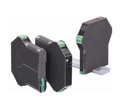
M6NYV ISOLATOR
M6NYV , M6DYV ISOLATOR Input/Output: 4-20 mA/4-20 mA, 4-20 mA/1-5 V, 1-5 V/4-20 mA, 1-5 V/1-5 V, ±10 V 24 Vdc powered Fast response 3.5 msec. optional with voltage output or 25 msec. optional with current output.
-
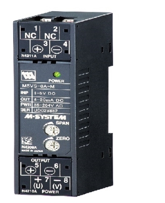
M5VS- AA-R Singal Transmitter
M5VS-AA-R Singal Transmitter Specific input range within ±300 V; current input with a resistor. 85-264 Vac or 24 Vdc powered (CE for 24 Vdc type) Fast response 25 msec. / <1 msec. optional
-
M3SYV ISOLATOR
M3SYV ISOLATOR Input 4-20 mA, 0-20 mA, ±20 mA, 0-10 V, 0-5 V, 1-5 V, ±10 V, ±5 V Output 4-20 mA, 0-20 mA, 0-10 V, 1-5 V, ±10 V 24 Vdc powered
-
M80YS OUTPUT ISOLATOR
M80YS OUTPUT ISOLATOR Input 1-5 V Output 4-20 mA, 0-20 mA, 0-10 V, 0-5 V, 1-5 V, ±10 V 24 Vdc powered Installation Base (model: M80BSx) This unit must be mounted on a dedicated base.
PRODUCTS LIST
- Signal Conditioners
- 2-wire Signal Conditioners
- Power Transducers
- Indicators
- Tower Lights
- Limit Alarms
- Gateway, Remote IO
- Paperless Recording System
- PC Recorder
- Web Data Loggers
- PID Control Components
- BA&Energy Monitoring Components
- Temperature Controllers
- Electric Actuators
- Lightning Surge Protectors
News Product
 IT40SW5F/6F, IT50SW5F/6F, IT60SW5F/6F Series")


STATISTIC
Visitor: 1063470Online: 17

