
")
R6S-DC4B PNP TRANSISTOR OUTPUT MODULE, 4


Tình trạng: In stock
Contact: 0989649965
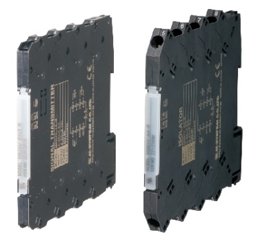
R6S-DC4B Remote I/O R6 Series PNP TRANSISTOR OUTPUT MODULE, 4 points
Số lượt xem: 1569
Detail
·Some details are not shown. Please refer to specification sheets for all information.
R6S-DC4B
Remote I/O R6 Series
PNP TRANSISTOR OUTPUT MODULE, 4 points
(PNP, Tension clamp)
Functions & Features
• 4-channel discrete output, compact size remote I/O module
MODEL: R6S–DC4B[1]
ORDERING INFORMATION
• Code number: R6S-DC4B[1]
Specify a code from below for [1].
(e.g. R6S-DC4B/Q)
• Specify the specification for option code /Q
(e.g. /C01)
[1] OPTIONS
blank: none
/Q: With options (specify the specification)
SPECIFICATIONS OF OPTION: Q
COATING (For the detail, refer to M-System's web site.)
/C01: Silicone coating
/C02: Polyurethane coating
RELATED PRODUCTS
• PC configurator software (model: R6CON)
Downloadable at M-System’s web site.
A dedicated cable is required to connect the module to the PC. Please refer to the internet software download site or the users manual for the PC configurator for applicable cable types.
GENERAL SPECIFICATIONS
Connection
Internal bus: Via the Installation Base (model: R6S-BS)
Output: Tension clamp
(Applicable wire size: 0.2 to 2.5 mm2, stripped length 8 mm)
Internal power: Via the Installation Base (model: R6S-BS)
Housing material: Flame-resistant resin (black)
Isolation: Output to internal bus or internal power
Module address: Selectable with DIP and rotary switches on the side
Output at the loss of communication: Selectable with the side DIP SW
Configuration mode: With DIP switches on the side panel
Power indicator: Green LED; Refer to the istruction manual for details.
Status indicator: Bi-color (red/green) LED;
Refer to the instruction manual for details.
Discrete output status indicators: Red LED;
Refer to the instruction manual for details.
OUTPUT
Common: Positive common (PNP) per 4 points
Number of I/O: Output, 4 points
Maximum outputs applicable at once: No limit (at 24 V DC)
Rated load voltage: 24 V DC ±10 %
Rated output current: 0.25 A per point, 2.0 A per common
Residual voltage: ≤ 1.2 V
Leakage current: ≤ 0.1 mA
ON delay: ≤ 0.5 msec.
OFF delay: ≤ 1.5 msec.
(When driving an inductive load, connect a diode in parallel with the load.)
INSTALLATION
Current consumption: 20 mA
Operating temperature: -10 to +55°C (14 to 131°F)
Operating humidity: 30 to 90 %RH (non-condensing)
Atmosphere: No corrosive gas or heavy dust
Mounting: Installation Base (model: R6S-BS)
Weight: 60 g (2.1 oz)
PERFORMANCE
Data allocation: 1
Insulation resistance: ≥ 100 MΩ with 500 V DC
Dielectric strength: 1500 V AC @ 1 minute
(output to internal bus or internal power to ground)
STANDARDS & APPROVALS
EU conformity:
EMC Directive
EMI EN 61000-6-4
EMS EN 61000-6-2
RoHS Directive
EN 50581
EXTERNAL VIEW
Refer to the instruction manual for setting procedures.
EXTERNAL DIMENSIONS & TERMINAL ASSIGNMENTS unit: mm (inch)
SCHEMATIC CIRCUITRY & CONNECTION DIAGRAM
M-System Co., Ltd.
Products
-

POWER SUPPLY MODULE R6N-PF1
R6N-PF1 Remote I/O R6 Series POWER SUPPLY MODULE
-

R6S-YS2 DC CURRENT OUTPUT MODULE
R6S-YS2 Remote I/O R6 Series DC CURRENT OUTPUT MODULE
-

R6S-TS2A THERMOCOUPLE INPUT MODULE
R6S-TS2A Remote I/O R6 Series THERMOCOUPLE INPUT MODULE
-

R6S-TS2 THERMOCOUPLE INPUT MODULE
R6S-TS2 Remote I/O R6 Series THERMOCOUPLE INPUT MODULE
-

R6S-SV2 DC VOLTAGE INPUT MODULE
R6S-SV2 Remote I/O R6 Series DC VOLTAGE INPUT MODULE
-

R6S-SS2 DC CURRENT INPUT MODULE
R6S-SS2 Remote I/O R6 Series DC CURRENT INPUT MODULE
-

R6S-RS2 RTD INPUT MODULE
R6S-RS2 Remote I/O R6 Series RTD INPUT MODULE
-
R6S-PF1 POWER SUPPLY MODULE
R6S-PF1 Remote I/O R6 Series POWER SUPPLY MODULE
-

R6N-YV2 DC VOLTAGE INPUT MODULE
R6N-YV2 Remote I/O R6 Series DC VOLTAGE INPUT MODULE
PRODUCTS LIST
- Signal Conditioners
- 2-wire Signal Conditioners
- Power Transducers
- Indicators
- Tower Lights
- Limit Alarms
- Gateway, Remote IO
- Paperless Recording System
- PC Recorder
- Web Data Loggers
- PID Control Components
- BA&Energy Monitoring Components
- Temperature Controllers
- Electric Actuators
- Lightning Surge Protectors
News Product
 IT40SW5F/6F, IT50SW5F/6F, IT60SW5F/6F Series")


STATISTIC
Visitor: 1054867Online: 15

