
")
Remote I/O R6 Series


Tình trạng: In stock
Contact: 0989649965
R6 Remote I/O R6 Series R6 SERIES GENERAL SPECIFICATIONS
Số lượt xem: 1131
Detail
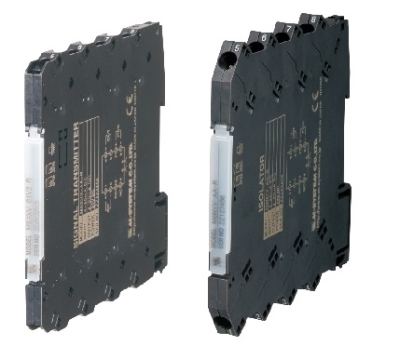
R6
Remote I/O R6 Series
R6 SERIES GENERAL SPECIFICATIONS
Functions & Features
• Free combination of analog and discrete I/O
• Direct sensor inputs
• Space-saving
• Low power consumption
Typical Applications
• Remote I/O for DCS and PLC
• Personal computer I/O
ORDERING INFORMATION
Refer to the specifications of the respective modules for details.
NETWORK MODULES: R6-[1]
Refer to the specifications of each module for details.
[1] I/O TYPE
NC1: CC-Link (Ver.1.10) (CE not available)
NC3: CC-Link (Ver.2.00, 64-point analog) (CE not available)
ND1: DeviceNet
NE1: Ethernet (Modbus/TCP, 32-point analog)
NE2: Ethernet (Modbus/TCP, 64-point analog)
NM1: Modbus (32-point analog)
NM2: Modbus (64-point analog)
NF1: T-Link (Fuji Electric) (CE not available)
(Select the Base model: R6x-BS8B)
(Select Power Supply Module model: R6x-PF1)
NP1: PROFIBUS-DP (62-point analog)
BASE: R6[1]-[2]
Refer to the specifications of each base for details.
[1] TERMINAL STYLE
D: Euro terminal
N: Screw terminal
S: Tension clamp
[2] FUNCTION
BS8A: 8 I/O slots + Network Module (18 mm wide)
BS8B: 8 I/O slots + Network Module (36.5 mm wide)
(Selectable only for using with R6-NF1, R6-NC3/W or R6-PSM)
BS8P: 8 I/O slots for extension
I/O MODULES: R6[1]-[2]
Refer to the specifications of each module for details.
[1] TERMINAL STYLE
D: Euro terminal
N: Screw terminal
S: Tension clamp
[2] FUNCTION
• I/O Module
SV2: DC voltage input, 2 points
SS2: DC current input, 2 points
TS2: Thermocouple input, 2 points
TS2A: Thermocouple input, 2 points, high-accuracy
(CE not available)
RS2: RTD input, 2 points
DS1: 4 – 20 mA input with 2-wire transmitter excitation
YV2: DC voltage output, 2 points
YS2: DC current output, 4 – 20 mA, 2 points
DA4: Discrete input, 4 points
DC4A: NPN transistor output, 4 points
DC4B: PNP transistor output, 4 points
• Blank Filler
DM: Blank filler module (CE not available)
POWER SUPPLY MODULES: R6[1]-PF1-R
Refer to the specifications of each module for details.
[1] TERMINAL STYLE
D: Euro terminal
N: Screw terminal
S: Tension clamp
FUNCTION
PF1: Power supply
POWER INPUT
R: 24 V DC
(Operational voltage range 24 V ±10 %, ripple 10 %p-p max.)
POWER SUPPLY MODULE: R6-PSM
Refer to the specifications of each module for details.
FUNCTION
PSM: Power supply module
(Select the Base model: R6x-BS8B)
(Not selectable with the T-Link module model: R6-NF1)
POWER INPUT
• AC power
100 - 240 AC (Operational voltage range: 90 - 264 V AC,
47 - 66 Hz)
FUNCTIONS & FEATURES
The R6 Series Remote I/O is composed of the power supply module, I/O modules, the network module and the base.
■ POWER SUPPLY MODULE
Converts 24 V DC power inputs for use in the network module and I/O modules.
■ I/O MODULES
Performs A/D conversion of field analog inputs; D/A conversion of data received through the internal bus into analog/discrete outputs.
■ NETWORK MODULE
Converts data between the open network fieldbus (Modbus, etc.) and the internal communication bus, functioning as a gateway between two buses.
■ BASE
Backplane with an internal communications bus and a power supply bus.
Basic 8-slot base (model: R6x-BS8A, R6x-BS8B) can be added with up to three (3) extension bases (model: R6x-BS8P) so that at the maximum of thirty-one (31) I/O modules can be mounted.
■ DATA CONVERSION
Varies depending on the types of I/O modules. Refer to the specifications of the respective I/O modules for details.
• Percent Data
The scaled input range of 0 – 100 % is converted into hexadecimal 0000 – 2710 (0 – 10000). The operational range is from -15 to +115% of the input range. When the signal exceeds the lower or upper limit of the operational range, the data is fixed at -15% or +115%. Negative value is represented in 2’s complements. The same applies to DC voltage or current output.
Note: The signal will remain within the operational range depending on the scaled 0% and 100% input values.
• Engineering Unit Data: Temperature
Temperature input (T/C or RTD) is converted into signed binary data which equals 10 times its engineering unit value (°C). For example, 25.5°C is converted into 255. For °F temperature unit, the integer part of raw data is directly adopted. That is, 135.4°F is converted into 135. Minus temperature is converted into negative value represented in 2’s complements.
■ SCALING & ZERO & SPAN ADJUSTMENTS
The PC Configurator Software (model: R6CON) is available to scale temperature and field I/O range into 0 – 100 %.
■ HOT SWAPPABLE I/O MODULES
Each I/O and network module has an independent CPU. Data is renewed by serial communications between modules. Removing or replacing modules does not adversely affect other modules on the same backplane. It is possible to replace them without removing the power supply.
RELATED PRODUCTS
• PC configurator software (model: R6CON)
Downloadable at M-System’s web site.
A dedicated cable is required to connect the module to the PC. Please refer to the internet software download site or the users manual for the PC configurator for applicable cable types.
GENERAL SPECIFICATIONS
Connection: Depends upon the type of modules. Refer to the specifications for the respective modules.
Housing material: Flame-resistant resin (black)
Internal communication bus:read rate Approx. 50 msec.
INSTALLATION
Current consumption: Depends upon the type of modules. Refer to the specifications for the respective modules.
Operating temperature: -10 to +55°C (14 to 131°F)
Operating humidity: 30 to 90 %RH (non-condensing)
Atmosphere: No corrosive gas or heavy dust
Construction: DIN rail or surface mounting
STANDARDS & APPROVALS
EU conformity:
EMC Directive
EMI EN 61000-6-4
EMS EN 61000-6-2
Low Voltage Directive
R6x-PF1
EN 61010-1,EN 61010-2-201
Measurement Category II (RUN contact output)
Pollution Degree 2
RUN contact output to internal bus or power
supply: Reinforced insulation (300 V)
R6-PSM
EN 61010-1,EN 61010-2-201
Measurement Category II (RUN contact output)
Installation Category II (power input)
Pollution Degree 2
Internal power or RUN contact output to power input to FG:
Reinforced insulation (300 V)
Internal power to RUN contact output: Basic insulation (300 V)
RoHS Directive
EN 50581
BASIC CONFIGURATIONS
■ EXTENSION BASE
Up to three (3) extension bases can be added to the basic one, so that at the maximum of thirty-one (31) I/O modules can be mounted. Certain network modules allow only less number of I/O modules to be mounted. Refer to the data sheet for the respective network modules for more information.
The terminal style of the extension bases must be the same as that for the basic one.
EXTERNAL DIMENSIONS unit: mm (inch)
MOUNTING REQUIREMENTS unit: mm (inch)
■ MOUNTING DIRECTION
The unit must be mounted on a vertical panel. Mounting in any other angle will cause internal temperature to rise,
may shorten the product’s life expectation or deteriorate its performance.
M-System Co., Ltd.
Products
-

POWER SUPPLY MODULE R6N-PF1
R6N-PF1 Remote I/O R6 Series POWER SUPPLY MODULE
-

R6S-YS2 DC CURRENT OUTPUT MODULE
R6S-YS2 Remote I/O R6 Series DC CURRENT OUTPUT MODULE
-

R6S-TS2A THERMOCOUPLE INPUT MODULE
R6S-TS2A Remote I/O R6 Series THERMOCOUPLE INPUT MODULE
-

R6S-TS2 THERMOCOUPLE INPUT MODULE
R6S-TS2 Remote I/O R6 Series THERMOCOUPLE INPUT MODULE
-

R6S-SV2 DC VOLTAGE INPUT MODULE
R6S-SV2 Remote I/O R6 Series DC VOLTAGE INPUT MODULE
-

R6S-SS2 DC CURRENT INPUT MODULE
R6S-SS2 Remote I/O R6 Series DC CURRENT INPUT MODULE
-

R6S-RS2 RTD INPUT MODULE
R6S-RS2 Remote I/O R6 Series RTD INPUT MODULE
-

R6S-PF1 POWER SUPPLY MODULE
R6S-PF1 Remote I/O R6 Series POWER SUPPLY MODULE
-
R6S-YV2 DC VOLTAGE OUTPUT MODULE
R6S-YV2 Remote I/O R6 Series DC VOLTAGE OUTPUT MODULE
PRODUCTS LIST
- Signal Conditioners
- 2-wire Signal Conditioners
- Power Transducers
- Indicators
- Tower Lights
- Limit Alarms
- Gateway, Remote IO
- Paperless Recording System
- PC Recorder
- Web Data Loggers
- PID Control Components
- BA&Energy Monitoring Components
- Temperature Controllers
- Electric Actuators
- Lightning Surge Protectors
News Product
 IT40SW5F/6F, IT50SW5F/6F, IT60SW5F/6F Series")


STATISTIC
Visitor: 1057579Online: 18

