
")
DeviceNet INTERFACE MODULE R6-ND1


Tình trạng: In stock
Contact: 0989649965
R6-ND1 Remote I/O R6 Series DeviceNet INTERFACE MODULE
Số lượt xem: 1550
Detail
R6-ND1
Remote I/O R6 Series
DeviceNet INTERFACE MODULE
Functions & Features
• Free combination of analog and discrete I/O
• Direct sensor inputs
• Space-saving
• Low power consumption
Typical Applications
• Remote I/O for DCS and PLC
MODEL: R6-ND1[1]
ORDERING INFORMATION
• Code number: R6-ND1[1]
Specify a code from below for [1].
(e.g. R6-ND1/Q)
• Specify the specification for option code /Q
(e.g. /C01)
[1] OPTIONS
blank: none
/Q: With options (specify the specification)
SPECIFICATIONS OF OPTION: Q
COATING (For the detail, refer to M-System's web site.)
/C01: Silicone coating
/C02: Polyurethane coating
RELATED PRODUCTS
• EDS file
(downloadable at M-System’s web site.)
GENERAL SPECIFICATIONS
Connection
DeviceNet: Euro type connector terminal
(applicable wire size: 0.2 to 2.5 mm2, stripped length
7 mm)
Internal bus: Via the Installation Base (model: R6x-BS)
Internal power: Via the Installation Base (model: R6x-BS)
Max. number of I/O modules: 32 (analog 64 points)
Isolation: DeviceNet to internal bus or internal power
Data allocation: Mode 1 or 2 set with the side DIP switch
DeviceNet COMMUNICATION
Transmission cable: Approved for DeviceNet
I/O data area size: Input and output data area size set with side DIP SW
Node address setting: DIP switch; 00 – 63
Baud rate setting: DIP switch
125 kbps, 250 kbps, 500 kbps
NS (Network Status) indicator: Bi-color (green/red) LED
indicates status of the communication link.
MS (Module Status) indicator: Bi-color (green/red) LED
indicates device status.
INSTALLATION
Supply voltage to network: 11 – 25 V DC supplied through the network terminal block
Supply current to network: 50 mA max.
Operating temperature: -10 to +55°C (14 to 131°F)
Operating humidity: 30 to 90 %RH (non-condensing)
Atmosphere: No corrosive gas or heavy dust
Mounting: Installation Base (model: R6x-BS)
Weight: 100 g (3.53 oz)
PERFORMANCE
Insulation resistance: ≥ 100 MΩ with 500 V DC
Dielectric strength: 2000 V AC @ 1 minute (DeviceNet to internal bus or internal power)
STANDARDS & APPROVALS
EU conformity:
EMC Directive
EMI EN 61000-6-4
EMS EN 61000-6-2
RoHS Directive
EN 50581
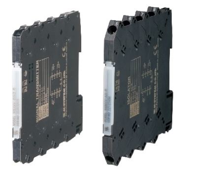
EXTERNAL VIEW
TRANSMISSION DATA DESCRIPTIONS
The DIP SW located at the side of the module switches the unit’s data allocation mode.
In the Data Allocation Mode 1, one (1) word is assigned per module. The second channel of analog I/O modules cannot be used.
In the Data Allocation Mode 2, two (2) words are assigned per module regardless of whether the second word area is required or not, even for discrete I/O modules that require one (1) word.
A maximum of 32 I/O modules can be mounted per node.
I/O DATA DESCRIPTIONS
EXTERNAL DIMENSIONS unit: mm (inch)
SCHEMATIC CIRCUITRY & CONNECTION DIAGRAM
M-System Co., Ltd.
Products
-

POWER SUPPLY MODULE R6N-PF1
R6N-PF1 Remote I/O R6 Series POWER SUPPLY MODULE
-

R6S-YS2 DC CURRENT OUTPUT MODULE
R6S-YS2 Remote I/O R6 Series DC CURRENT OUTPUT MODULE
-

R6S-TS2A THERMOCOUPLE INPUT MODULE
R6S-TS2A Remote I/O R6 Series THERMOCOUPLE INPUT MODULE
-

R6S-TS2 THERMOCOUPLE INPUT MODULE
R6S-TS2 Remote I/O R6 Series THERMOCOUPLE INPUT MODULE
-

R6S-SV2 DC VOLTAGE INPUT MODULE
R6S-SV2 Remote I/O R6 Series DC VOLTAGE INPUT MODULE
-

R6S-SS2 DC CURRENT INPUT MODULE
R6S-SS2 Remote I/O R6 Series DC CURRENT INPUT MODULE
-

R6S-RS2 RTD INPUT MODULE
R6S-RS2 Remote I/O R6 Series RTD INPUT MODULE
-

R6S-PF1 POWER SUPPLY MODULE
R6S-PF1 Remote I/O R6 Series POWER SUPPLY MODULE
-
R6S-YV2 DC VOLTAGE OUTPUT MODULE
R6S-YV2 Remote I/O R6 Series DC VOLTAGE OUTPUT MODULE
PRODUCTS LIST
- Signal Conditioners
- 2-wire Signal Conditioners
- Power Transducers
- Indicators
- Tower Lights
- Limit Alarms
- Gateway, Remote IO
- Paperless Recording System
- PC Recorder
- Web Data Loggers
- PID Control Components
- BA&Energy Monitoring Components
- Temperature Controllers
- Electric Actuators
- Lightning Surge Protectors
News Product
 IT40SW5F/6F, IT50SW5F/6F, IT60SW5F/6F Series")


STATISTIC
Visitor: 1064901Online: 19

