
")
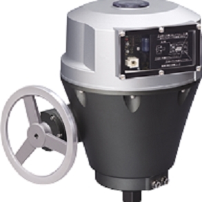
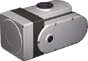
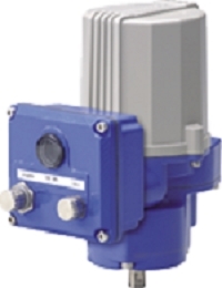
MRP5 MINI-TOP ELECTRONIC ACTUATOR


Tình trạng: In stock
Contact: 0989649965
MRP5 Final Control Elements MINI-TOP ELECTRONIC ACTUATOR
Số lượt xem: 1146
Detail
·Some details are not shown. Please refer to specification sheets for all information.
MRP5
Final Control Elements
MINI-TOP ELECTRONIC ACTUATOR
(rotary type)
Functions & Features
• Small-size control valve actuator
• 1/1000 high resolution
• Easy adjustment: electronic limiter at the valve open & closed positions
• Overload protection
• Various power inputs
Typical Applications
• Actuator for automatic control valve in pilotplants
• Air-conditioning in buildings or plants
• Micro-flow control for pharmaceutical injection
• For small-size control valves
MODEL: MRP5–14[1][2]–[3][4][5]
ORDERING INFORMATION
• Code number: MRP5-14[1][2]-[3][4][5]
Specify a code from below for each of [1] through [5].
(e.g. MRP5-14LT-A0R)
• Special input range (for codes Z and 0)
SPAN
1: 45 to 90 degrees
OPERATION TIME, TORQUE
4: 13 seconds / 90°, 10 N·m
[1] SEQUENTIAL CONTROL SIGNALS
L: Full-open/-closed signal
F: Forced open/close signal
B: Full-open/-closed and forced open/close signals
(Select 'With Terminal Box.')
0: Without
[2] TERMINAL BOX
T: With
0: Without
[3] INPUT
Current
A: 4 – 20 mA DC (Input resistance 250 Ω)
Z: Specify current (See INPUT SPECIFICATIONS)
Voltage
6: 1 – 5 V DC (Input resistance approx. 1 MΩ)
0: Specify voltage (See INPUT SPECIFICATIONS)
[4] CE MARKING
C: With
0: Without
[5] POWER INPUT
AC Power
K3: 100 – 120 V AC
(Operational voltage range 90 – 132 V, 47 – 66 Hz)
(Not selectable for CE)
L3: 200 – 240 V AC
(Operational voltage range 180 – 264 V, 47 – 66 Hz)
(Not selectable for CE)
DC Power
R: 24 V DC
(Operational voltage range 24 V ±10 %, ripple 10 %p-p max.)
GENERAL SPECIFICATIONS
Degree of protection: IP66
Action: Direct or reverse; field selectable with DIP switches (factory set to “reverse”)
(In “reverse” action, the output stem seen from the cover turns counterclockwise with an input signal increase.)
Operation at abnormally low input: Counterclockwise turn, clockwise turn or stop; field selectable with DIP switches (factory set to“clockwise”)
Note: Counterclockwise or clockwise if seen from the cover.
Detectable input drop level: -16 ±2.5 %
Electrical connection
•Without terminal box
Wiring conduit: G 1/2 female; cable connector with 1 meter wire (0.5 mm2) provided
•Terminal box
Wiring conduit: G 1/2 female (two)
Terminal screws: M3 pillar terminal
(Sequential control signal suffix code B)
M3 chromated steel
(other terminal box types)
(torque 0.5 N·m)
Housing material: Diecast aluminum
Drive: Stepping motor
Insulation class: E
Position detection: Potentiometer
Deadband: 0.1 – 4.5 % adjustable (factory set to 1.5 %)
Restarting timer: 0 – 10 sec. adjustable
(factory set to 1.5 sec.)
Isolation: AC power to signal
Zero adjustment: 0 – 25 %
Span adjustment: 50 - 100 %
Protective functions: Overload protection
Power indicator: Green LED turns on with power supplied.
Input indicator: Green LED turns on with normal input
Status indicator LED: Red light blinks in 2 sec. intervals in normal operations; blinks in 0.5 sec. intervals when a foreign object is detected mechanically caught inside.
Manual operating handle: Not available
INPUT SPECIFICATIONS
■ DC Current: Input resistor incorporated (250 Ω)
■ DC Voltage: 1 – 5 V DC or specific range within 0 – 5 V DC, minimum span 1 V
(For a current input, convert the current to a voltage with 250 Ω)
Input resistance: Approx. 1 MΩ
■ Forced open/close signal:
Dry contact inputs to command clockwise and counterclockwise turns
Rating: 5 V DC @ 2.5 mA
OUTPUT SPECIFICATIONS
■ Operation Time & Torque (at rated power voltage)
MRP5-14: 13 sec. / 90°; 10 N·m (7.38 ft·lbf)
■ DC Voltage: 1 – 5 V DC (not isolated)
With “direct” action, 5 – 1 V DC position output is provided proportionally to 4 – 20 mA DC (1 – 5 V DC) input.
Load resistance: ≥ 5 kΩ
■ Full-open / -closed signals: Limit switch contact
Rating: 125 V AC @ 0.75 A (cos ø = 1)
30 V DC @ 0.6 A (resistive load)
Mechanical life: 3 × 10⁷ cycles
Maximum operation frequency: 60 cycles/min.
INSTALLATION
Power consumption
•AC: Approx. 25 VA
•DC: Approx. 0.6 A
Operating temperature: -5 to +55°C (23 to 131°F)
Operating humidity: 30 to 85 %RH (non-condensing)
Vibration: 0.5 G (4.9 m/s2) max.
Mounting position: All directions
Do not mount the actuator with its output stem or cable connector on the upside if the actuator is to be exposed to dripping water.
Weight
DC powered: 1.5 kg (3.31 lb)
AC powered: 1.7 kg (3.75 lb)
Add 0.7 kg (1.54 lb) for the terminal box.
PERFORMANCE
Resolution: 1/1000 or 0.09°, whichever is greater, with 0.1 % deadband setting
Insulation resistance
•AC powered: ≥ 100 MΩ with 500 V DC
(signal or metallic housing to power)
≥ 100 MΩ with 100 V DC
(signal to metallic housing)
•DC powered: ≥ 100 MΩ with 100 V DC
(signal or power to metallic housing)
Dielectric strength
•AC powered: 1500 V AC @ 1 minute
(signal or metallic housing to power)
100 V AC @ 1 minute
(signal to metallic housing)
•DC powered: 100 V AC @ 1 minute
(signal or power to metallic housing)
STANDARDS & APPROVALS
EU conformity:
EMC Directive
EMI EN 61000-6-4
EMS EN 61000-6-2
Low Voltage Directive
EN 61010-1
Measurement Category II (Full-open/-closed signal)
Pollution Degree 2
Full-open/-closed signal to other, power or metallic
housing: Reinforced insulation (125 V)
RoHS Directive
EN 50581
TERMINOLOGY
• Overload (Lock) Protection
The Mini-Top Series is equipped with a protection circuit against overload caused by for example the valve catching an alien substance.
When an overload is detected, the Mini-Top stops supplying power to the motor and the status LED blinks in 0.5 sec. intervals.
The protection is reset automatically with applying opposite-direction input signal or turning the power off and restarting.
• Restarting Timer
The Mini-Top Series is equipped with a timer circuit which gives an interval period (0 – 10 seconds) between stop-restart actions to prevent the motor and other internal components from overheating.
It is recommended to set a long restarting time when the ambient temperature and/or the temperature of flow material is high.
• Electronic Limiter
This model is equipped with electronic limiters in order to prevent mechanical locks when the input goes below 0 % or above 100 %.
Limiters are set at approx. -0.5 % for the full-closed side, approx. 100.5 % for the full-open side.
TERMINAL CONNECTIONS
EXTERNAL DIMENSIONS unit: mm (inch)
SCHEMATIC CIRCUITRY
M-System Co., Ltd.
Products
-
PRP-2 SERVO-TOP II ELECTRONIC ACTUATOR
PRP-2 Final Control Elements SERVO-TOP II ELECTRONIC ACTUATOR (rotary type; max. torque 600 N·m)
-

PRP SERVO-TOP II ELECTRONIC ACTUATOR
PRP Final Control Elements SERVO-TOP II ELECTRONIC ACTUATOR (rotary type; max. torque 200 N·m)
-
PRP SERVO-TOP II ELECTRONIC ACTUATOR
PRP Final Control Elements Lloyd's Register approved SERVO-TOP II ELECTRONIC ACTUATOR
-
MRP6D MINI-TOP ELECTRONIC ACTUATOR
MRP6D Final Control Elements MINI-TOP ELECTRONIC ACTUATOR
-

MRP6C MINI-TOP ELECTRONIC ACTUATOR
MRP6C Final Control Elements MINI-TOP ELECTRONIC ACTUATOR
-
MRP6 MINI-TOP ELECTRONIC ACTUATOR
MRP6 Final Control Elements MINI-TOP ELECTRONIC ACTUATOR
-
MRP5D MINI-TOP ELECTRONIC ACTUATOR
MRP5D Final Control Elements MINI-TOP ELECTRONIC ACTUATOR
-

MRP5C2 MINI-TOP ELECTRONIC ACTUATOR
MRP5C2 Final Control Elements MINI-TOP ELECTRONIC ACTUATOR
-

MRP5C MINI-TOP ELECTRONIC ACTUATOR
MRP5C Final Control Elements MINI-TOP ELECTRONIC ACTUATOR
PRODUCTS LIST
- Signal Conditioners
- 2-wire Signal Conditioners
- Power Transducers
- Indicators
- Tower Lights
- Limit Alarms
- Gateway, Remote IO
- Paperless Recording System
- PC Recorder
- Web Data Loggers
- PID Control Components
- BA&Energy Monitoring Components
- Temperature Controllers
- Electric Actuators
- Lightning Surge Protectors
News Product
 IT40SW5F/6F, IT50SW5F/6F, IT60SW5F/6F Series")


STATISTIC
Visitor: 1045924Online: 6

