
")
M3LT T/C input, PC & "One-Step Cal" programmable


Tình trạng: In stock
Contact: 0989649965
M3LT T/C input, PC & "One-Step Cal" programmable Input: K, E, J, T, B, R, S, C, N, U, L, PL-II selectable Output selectable within 0-20 mA and ±10 V 10-32 Vdc powered DIP switch or PC configuration 300-point linearization using the PC Configurator
Số lượt xem: 1176
Detail
Products
-

M2RT - RTD input, fixed range
M2RT - RTD input, fixed range Specify Pt100, Pt50, Ni508.4 and temp. range. Special RTD acceptable 100-240 Vac or 24 Vdc powered Fast response 25 msec. optional Operating temperature: -20 to +80 °C (-4 to +176°F)
-
W5RS - RTD input signal splitter, fixed range, low cost
W5RS - RTD input signal splitter, fixed range, low cost
-

W2XR RTD input signal splitter, PC programmable
RTD input signal splitter, PC programmable W2XR Input: Pt100, Pt1000, Pt50, Cu10 selectable Output selectable within 0-20 mA and ±10 V 100-240 Vac or 24 Vdc powered
-
M2TT - T/C input, fixed range
M2TT - T/C input, fixed range Specify K, E, J, T, B, R, S, N and temp. range. Special T/C acceptable 100-240 Vac or 24 Vdc powered Fast response 25 msec. optional Operating temperature: -20 to +80 °C (-4 to +176°F)
-

W2XT - T/C input signal splitter, PC programmable
W2XT - T/C input signal splitter, PC programmable
-

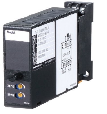
M5TS - T/C input, fixed range, low cost
M5TS - T/C input, fixed range, low cost Specify K, E, J, T, B, R, S, N and temp. range. Special T/C acceptable 100-240 Vac or 24 Vdc powered (CE for 24 Vdc type) Fast response 25 msec. optional
-
M5RS - RTD input, fixed range, low cost
M5RS - RTD input, fixed range, low cost Specify Pt100, Pt50, Ni508.4 and temp. range. Special RTD acceptable 100-240 Vac or 24 Vdc powered (CE for 24 Vdc type) Fast response 25 msec. optional
-

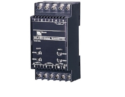
W2TS T/C input signal splitter, fixed range
W2TS T/C input signal splitter, fixed range Specify K, E, J, T, B, R, S, N and temp. range. Special T/C acceptable Independent current/voltage output ranges can be specified 100-240 Vac or 24 Vdc powered Fast response 25 msec. optional UL/cUL Class I, Div. 2 approval
-

W2RS1 RTD input signal splitter, fixed range
W2RS1 RTD input signal splitter, fixed range Specify Pt100, Pt50, Ni508.4 and temp. range. Special RTD acceptable Independent current/voltage output ranges can be specified 100-240 Vac or 24 Vdc powered Fast response 25 msec. optional 1 mA sensing current (except Cu Input)
PRODUCTS LIST
- Signal Conditioners
- 2-wire Signal Conditioners
- Power Transducers
- Indicators
- Tower Lights
- Limit Alarms
- Gateway, Remote IO
- Paperless Recording System
- PC Recorder
- Web Data Loggers
- PID Control Components
- BA&Energy Monitoring Components
- Temperature Controllers
- Electric Actuators
- Lightning Surge Protectors
News Product
 IT40SW5F/6F, IT50SW5F/6F, IT60SW5F/6F Series")


STATISTIC
Visitor: 1071279Online: 17

