

")
M2XU


Tình trạng: In stock
Contact: 0989649965
M2XU Signal Conditioners M-system Vietnam
Số lượt xem: 2171
Detail
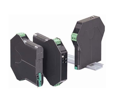
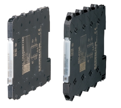
M2XU - Signal Conditioners Mini-M Series
UNIVERSAL TRANSMITTER
(PC programmable)
Functions & Features
• Accepts direct inputs from various sensors and provides a standard process signal
• I/O types and calibration ranges are fully programmable via a PC
• Linearization up to 100 points can be programmed
for DC and potentiometer inputs
• Isolation between input – output – power
Typical Applications
• Signal conversion between control room and field instrumentation with isolation
• Ideal for use as a fast solution, multifunctional spare part
MODEL: M2XU–[1][2]–[3][4]
ORDERING INFORMATION
• Code number: M2XU-[1][2]-[3][4]
Specify a code from below for each [1] through [4].
(e.g. M2XU-00-R/CE/Q)
• Specify the specification for option code /Q
(e.g. /C01/S01)
Non-specified orders will be shipped at default factory settings (M2XU-00: 4 – 20 mA input/4 – 20 mA output). However, the power suffix code must be specified.
If you specify full code numbers without specific calibration ranges, default settings will be used.
[1] INPUT
0: User-calibrated (Factory default: 4 – 20 mA DC)
If the unit is to be factory-calibrated to a specific
input type, please select from the following:
Current
Z1: Range 0 – 50 mA DC (Input resistance 100 Ω)
Voltage
S1: Range -1 – +1 V DC (Input resistance 1 MΩ min.)
S2: Range -10 – +10 V DC (Input resistance 1 MΩ min.)
Thermocouple
T1: (PR) (Usable Range 0 to 1760°C, 32 to 3200°F)
T2: K (CA) (Usable range -270 to +1370°C, -454 to +2498°F)
T3: E (CRC) (Usable range -270 to +1000°C, -454 to +1832°F)
T4: J (IC) (Usable range -210 to +1200°C, -346 to +2192°F)
T5: T (CC) (Usable range -270 to +400°C, -454 to +752°F)
T6: B (RH) (Usable range 0 to 1820°C, 32 to 3308°F)
T7: R (Usable range -50 to +1760°C, -58 to +3200°F)
T8: S (Usable range -50 to +1760°C, -58 to +3200°F)
T9: C (WRe 5-26) (Usable range 0 to 2315°C, 32 to 4199°F)
TN: N (Usable range -270 to +1300°C, -454 to +2372°F)
TU: U (Usable range -200 to +400°C, -328 to +752°F)
TL: L (Usable range -200 to +900°C, -328 to +1652°F)
TP: P (Platinel II) (Usable range 0 to 1395°C, 32 to 2543°F)
T0: Specify (Please provide an emf table.)
RTD
(2- or 3-wire)
R1: JPt 100 (JIS'89)
(Usable range: -200 to +500°C, -328 to +932°F)
R3: Pt 100 (JIS'89)
(Usable range: -200 to +850°C, -328 to +1562°F)
R4: Pt 100 (JIS'97, IEC)
(Usable range: -200 to +850°C, -328 to +1562°F)
R5: Pt 50 Ω (JIS'81)
(Usable range: -200 to +649 °C, -328 to +1200°F)
R6: Ni 508.4 Ω
(Usable range: -50 to +200°C, -58 to +392°F)
R7: Pt 1000
(Usable range: -200 to +200°C, -328 to +392°F)
R8: Ni 100 (Usable range: -50 to +200°C, -58 to +392°F)
R9: Cu 10 @25°C
(Usable range: -50 to +200°C, -58 to +392°F)
R0: Specify (Please provide a resistance table.)
Potentiometer
M: Total resistance 100 Ω – 10 kΩ
Note: Consult M-System for 2-wire RTD
[2] OUTPUT
0: User-calibrated (Factory default: 4 – 20 mA DC)
If the unit is to be factory-calibrated to a specific
output type, please select from the following:
Current
Z1: Range 0 – 20 mA DC
Voltage
V1: Range -2.5 – +2.5 V DC
V2: Range -10 – +10 V DC
[3] POWER INPUT
AC Power
M2: 100 – 240 V AC (Operational voltage range 85 – 264 V,
47 – 66 Hz)
(90 – 264 V for UL)
DC Power
R: 24 V DC
(Operational voltage range 24 V ±10 %, ripple 10 %p-p max.)
P: 110 V DC
(Operational voltage range 85 – 150 V, ripple 10 %p-p max.)
(110 V ±10 % for UL)
[4] OPTIONS (multiple selections)
Standards & Approvals (must be specified)
/N: Without CE or UL
/CE: CE marking
/UL: UL approval, CE marking
Other Options
blank: none
/Q: Option other than the above (specify the specification)
SPECIFICATIONS OF OPTION: Q (multiple selections)
COATING (For the detail, refer to M-System's web site.)
/C01: Silicone coating
/C02: Polyurethane coating
/C03: Rubber coating (UL not available)
TERMINAL SCREW MATERIAL
/S01: Stainless steel (UL not available)
RELATED PRODUCTS
• PC configurator software (model: JXCON)
Downloadable at M-System’s web site.
A dedicated cable is required to connect the module to the PC. Please refer to the internet software download site or the users manual for the PC configurator for applicable cable types.
GENERAL SPECIFICATIONS
Construction: Plug-in
Connection: M3 screw terminals (torque 0.8 N·m)
Screw terminal: Chromated steel (standard) or stainless steel
Housing material: Flame-resistant resin (black)
Isolation: Input to output to power
Overrange output: Approx. -15 to +115 %
(Negative current output is not provided.)
Manual zero adjustments: -5 to +5 %
(factory setting: 0 %)
Manual span adjustments: 95 to 105 %
(factory setting: 100 %)
Programming: PC programmable features include:
· T/C and RTD type and temp. range
· Input and output ranges
· Zero and span adjustments
· Simulated output
· User's linearization table (max. 100 points, specified within -15 – +115 % for both input and output)
· User’s TC/RTD table
Burnout (T/C, RTD and Pot.): Upscale standard; downscale or no burnout options are PC programmable
Linearization (T/C, RTD input): Standard tables stored in memory
Cold junction compensation (T/C): CJC sensor (included) to be attached to the input terminals
Status indicator LED: Blinking patterns indicate different operating status of the transmitter.
Configurator connection: 2.5 dia. miniature jack;
RS-232-C level
INPUT SPECIFICATIONS
■ DC Current: Shunt resistor attached to the input terminals (0.5 W)
Operational range: 0 – 70 mA DC with 100 Ω, 0.5 W
Input range: 0 – 50 mA DC
Minimum span: 2 mA
Offset: Lower range can be any specific value within the input range provided that the minimum span is maintained.
If not specified, the input range is 4 – 20 mA DC.
■ DC Voltage
Operational range: -11.5 – +11.5 V DC
Input range: -10 – +10 V DC
Minimum span: 10 mV for S1; 100 mV for S2
Offset: Lower range can be any specific value within the input range provided that the minimum span is maintained.
If not specified, the input range is shown below.
S1: 0 – 100 mV DC
S2: 1 – 5 V DC
■ Thermocouple
For T/C types K, E, T, B, R, S or N, the accuracy in the temperature ranges near the lower limit may be out of the described value. Consult M-System for more detail.
Input resistance: 1 MΩ min.
Burnout sensing: 45 nA ±10 %
Offset: Lower range can be any specific value within the input range provided that the minimum span is maintained.
If not specified, the input range is shown below.
T1 PR: 0 – 1600°C
T2 K: 0 – 1000°C
T3 E: 0 – 500°C
T4 J: 0 – 500°C
T5 T: 0 – 300°C
T6 B: 0 – 1800°C
T7 R: 0 – 1600°C
T8 S: 0 – 1600°C
T9 C: 0 – 2000°C
TN N: 0 – 1000°C
TU U: 0 – 300°C
TL L: 0 – 500°C
TP P: 0 – 1200°C
■ RTD
Maximum leadwire resistance: 200 Ω per wire (3 -wire)
Sensing current: ≤ 1.0 mA
If not specified, the input range is shown below.
R1: JPt 100 0 – 100°C
R3: Pt 100 0 – 100°C
R4: Pt 100 0 – 100°C
R5: Pt 50 Ω 0 – 200°C
R6: Ni 508.4 Ω 0 – 100°C
R7: Pt 1000 0 – 100°C
R8: Ni 100 0 – 100°C
R9: Cu 10 0 – 100°C
•Potentiometer: 100 Ω – 10 kΩ
Minimum span:
(Range) 0 – 100 Ω : 2.5 Ω
0 – 300 Ω : 3.0 Ω
0 – 1000 Ω : 10 Ω
0 – 10 kΩ : 10 Ω
Excitation: ≤ 0.5 V DC at 1000 Ω
If not specified, the input range is 0 – 1000 Ω.
OUTPUT SPECIFICATIONS
■ DC Current
Operational range: 0 – 24 mA DC
Output range: 0 – 20 mA DC
Minimum span: 1 mA
Offset: Lower range can be any specific value within the output range provided that the minimum span is maintained.
Load resistance: Output drive 15 V max.
(e.g. 4 – 20 mA: 750 Ω [15 V ÷ 20 mA])
If not specified, the output range is 4 – 20 mA DC.
■ DC Voltage
Code V1 (narrow spans)
Operational range: -3 – +3 V DC
Output range: -2.5 – +2.5 V DC
Minimum span: 250 mV
Code V2 (wide spans)
Operational range: -11.5 – +11.5 V DC
Output range: -10 – +10 V DC
Minimum span: 1 V
Offset: Lower range can be any specific value within the output range provided that the minimum span is maintained.
Load resistance: Output drive 1 mA max.
(e.g. 1 – 5 V: 5000 Ω [5 V ÷ 1 mA])
If not specified, the output range is shown below.
V1: 0 – 1 V DC
V2: 1 – 5 V DC
INSTALLATION
Power Consumption
•AC: Approx. 6 VA
•DC: Approx. 3 W
Operating temperature: -30 to +60°C (-22 to +140°F)
Operating humidity: 30 to 90 %RH (non-condensing)
Mounting: Surface or DIN rail
Weight: 120 g (0.26 lb)
PERFORMANCE
Accuracy: Input accuracy + output accuracy
Input accuracy (% of input range)
Inversely proportional to span.
(DC) -1 – +1 V : ±0.02
-10 – +10 V : ±0.02
0 – 50 mA : ±0.02
Except the input resistor error.
(T/C) (PR) : ±0.08
K (CA) : ±0.02
E (CRC) : ±0.02
J (IC) : ±0.04
T (CC) : ±0.06
B (RH) : ±0.12
R : ±0.08
S : ±0.08
C (WRe 5 - 26) : ±0.04
N : ±0.04
U : ±0.04
L : ±0.04
P (Platinel II) : ±0.04
(RTD) JPt 100 (JIS ’89) : ±0.04
Pt 100 (JIS ’89) : ±0.03
Pt 100 (JIS ’97, IEC) : ±0.03
Pt 50 Ω (JIS ’81) : ±0.04
Ni 508.4 Ω : ±0.05
Pt 1000 : ±0.08
Ni 100 : ±0.14
Cu 10 : ±0.6
(Pot.) 0 – 100 Ω : ±0.08
0 – 300 Ω : ±0.04
0 – 1000 Ω : ±0.04
0 – 10 kΩ : ±0.04
Output accuracy: ±0.02 % of output range
Inversely proportional to span.
Cold junction compensation error:
±0.4°C or ±0.7°F (at 20°C ±10°C or 68°F ±18°F)
Temp. coefficient
(at -5 to +55°C [23 to 131°F] of I/O range)
Input: ±0.016 %/°C (±0.009 %/°F) with current
±0.004 %/°C (±0.002 %/°F) with voltage
±0.004 %/°C (±0.002 %/°F) with T/C
±0.004 %/°C (±0.002 %/°F) with RTD
±0.004 %/°C (±0.002 %/°F) with Pot.
Output: ±0.013 %/°C (±0.007 %/°F)
Response time:
≤ 0.5 sec.(0 – 90 %) with current
≤ 0.5 sec.(0 – 90 %) with voltage
≤ 1.5 sec.(0 – 90 %) with T/C
≤ 0.9 sec.(0 – 90 %) with RTD
≤ 0.9 sec. (0 – 90 %) with Pot.
Burnout response: ≤ 10 sec.
Line voltage effect: ±0.1 % over voltage range
Insulation resistance: ≥ 100 MΩ with 500 V DC
Dielectric strength: 2000 V AC @1 minute (input to output to power to ground)
CALCULATION EXAMPLES OF OVERALL ACCURACY
[Example] Input Type -10 – +10 V, Input Range 1 – 5 V, Output Type 0 – 20 mA, Output Range 0 – 10 mA
Max. Input Range (20 V) ÷ Span (4 V) × 0.02 % = 0.1 %
Max. Output Range (20 mA) ÷ Span (10 mA) × 0.02 % = 0.04 %
Overall accuracy = 0.1 + 0.04 = ±0.14 %
STANDARDS & APPROVALS
EU conformity:
EMC Directive
EMI EN 61000-6-4
EMS EN 61000-6-2
Low Voltage Directive
EN 61010-1
Installation Category II
Pollution Degree 2
Input or output to power: Reinforced insulation (300 V)
Input to output: Basic insulation (300 V)
RoHS Directive
EN 50581
Approval:
UL/C-UL nonincendive Class I, Division 2,
Groups A, B, C, and D
(ANSI/ISA-12.12.01, CAN/CSA-C22.2 No.213)
UL/C-UL general safety requirements
(UL 61010-1, CAN/CSA-C22.2 No.61010-1)
EXTERNAL VIEW
Refer to the instruction manual for detailed procedures.
EXTERNAL DIMENSIONS unit: mm (inch)
TERMINAL ASSIGNMENTS unit: mm (inch)
Use the input resistor (model: REM2) for a DC current input,
and the CJC sensor (model: CJM) for a thermocouple input,
both included in the package.
M-System Vietnam
PRODUCTS LIST
- Signal Conditioners
- 2-wire Signal Conditioners
- Power Transducers
- Indicators
- Tower Lights
- Limit Alarms
- Gateway, Remote IO
- Paperless Recording System
- PC Recorder
- Web Data Loggers
- PID Control Components
- BA&Energy Monitoring Components
- Temperature Controllers
- Electric Actuators
- Lightning Surge Protectors
News Product
 IT40SW5F/6F, IT50SW5F/6F, IT60SW5F/6F Series")


STATISTIC
Visitor: 1058388Online: 24

