
")
M2EAXV DC ALARM (PC programmable, dual or quad alarm trip


Tình trạng: Out stock
Contact: 0989649965
M2EAXV
Số lượt xem: 6893
Detail
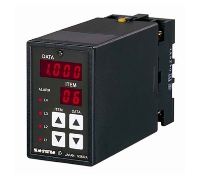
M2EAXV Super-mini Signal Conditioners with Display Mini-M M2E Series
DC ALARM
(PC programmable, dual or quad alarm trip)
Functions & Features
• Provides relay outputs at preset DC input levels
• Quad or dual trip
• Front LCD display indicating values in scaled engineering unit range is used to program the module
• Adjustable deadband (hysteresis)
• ON delay time selectable
• Hi/Lo trip and energized/de-energized coil independently selectable for each setpoint
• Settable with front button
• Enclosed relays
• Relays can be powered by 200 V AC and 100 V DC
• High-density mounting on DIN rail
Typical Applications
• Annunciator
• Various alarm applications
MODEL: M2EAXV–[1]-[2][3]
ORDERING INFORMATION
• Code number: M2EAXV-[1]-[2][3]
Specify a code from below for each [1] through [3].
(e.g. M2EAXV-2-M2/Q)
• Specify the specification for option code /Q
(e.g. /C01/S01/SET)
INPUT – Field-selectable
◆ DC Input
• Current input: 0 - 50 mA DC
• Voltage input: -1000 - +1000 mV DC
• Voltage input: -10 - +10 V DC
[1] OUTPUT
2: 4 points; N.O. or make contact
3: 4 points; N.C. or break contact
5: 2 points; SPDT or transfer contact
[2] POWER INPUT
AC Power
M2: 100 – 240 V AC (Operational voltage range 85 – 264 V,
47 – 66 Hz)
DC Power
R: 24 V DC
(Operational voltage range 24 V ±10 %, ripple 10 %p-p max.)
P: 110 V DC
(Operational voltage range 85 – 150 V, ripple 10 %p-p max.)
[3] OPTIONS
blank: none
/Q: With options (specify the specification)
SPECIFICATIONS OF OPTION: Q (multiple selections)
COATING (For the detail, refer to M-System's web site.)
/C01: Silicone coating
/C02: Polyurethane coating
/C03: Rubber coating
TERMINAL SCREW MATERIAL
/S01: Stainless steel
EX-FACTORY SETTING
/SET: Preset according to the Ordering Information Sheet
(No. ESU-5146)
Default setting will be used if not otherwise specified.
RELATED PRODUCTS
• M2EA configurator software (model: M2EACFG)
Downloadable at M-System’s web site.
A dedicated cable is required to connect the module to the PC. Please refer to the internet software download site or the users manual (EM-5151) for the M2EA configurator for applicable cable types.
GENERAL SPECIFICATIONS
Construction: Plug-in
Connection: M3 screw terminals (torque 0.8 N·m)
Screw terminal: Chromated steel (standard) or stainless steel
Housing material: Flame-resistant resin (gray)
Isolation: input to L1 or L4 alarm output to L2 or L3 alarm output to power
(for output code 5, L3 alarm output and L4 alarm output is not available)
Configuration: Program with front buttons or Via PC.
Programmable features include: Refer to the parameter list.
Configurator connection: 2.5 dia. miniature jack;
RS-232-C level
DISPLAY
Display functions: Displays and sets measured range, engineering unit
Display size: Approx. 15.6 × 20.8 mm (0.61” × 0.82”)
Number of pixels: 68 × 95 (horizontal × vertical)
Character color: Yellow (reversing display of the current value and the alarm setting value when alarm is tripped)
Display life: Approx. 60000 hours
(Expected time for the Display brightness to be reduced to 50 % when the Display is used continuously with brightness setting 2 in 25 ℃)
Display type: OEL display
Display digit: Negative 5 digits, positive 6 digits (-99999 to 999999)
Decimal point position: Selectable
INPUT SPECIFICATIONS
■ DC Current
Input resistance: Incorporated (23 Ω)
Input range: 0 - 50 mA DC
Minimum span: 2 mA
Offset: Lower range can be any specific value within the input range provided that the minimum span is maintained.
The measurement available for -5 - +105% of input setting range.
■ DC Voltage
•Narrow Spans (mV)
Input range: -1000 – +1000 mV DC
Minimum span: 100 mV
•Wide Spans (V)
Input range: -10 – +10 V DC
Minimum span: 1 V
Offset: Lower range can be any specific value within the input range provided that the minimum span is maintained.
Input resistance: 1 MΩ minimum
The measurement available for -5 - +105% of input setting range.
OUTPUT SPECIFICATIONS
■ Quad Alarm
Relay rating: 100 V AC @ 1 A (cos ø = 1)
120 V AC @ 1 A (cos ø = 1)
240 V AC @ 0.5 A (cos ø = 1)
30 V DC @ 1 A (resistive load)
Maximum switching voltage: 250 V AC or 125 V DC
Maximum switching power: 120 VA or 30 W
Minimum load: 5 V DC @ 10 mA
Mechanical life: 5 × 10⁷ cycles
■ DUAL ALARM
Relay rating: 100 V AC @ 4 A (cos ø = 1)
120 V AC @ 4 A (cos ø = 1)
240 V AC @ 2 A (cos ø = 1)
30 V DC @ 4 A (resistive load)
Maximum switching voltage: 250 V AC or 125 V DC
Maximum switching power: 480 VA or 150 W
Minimum load: 5 V DC @ 10 mA
Mechanical life: 5 × 10⁷ cycles
INSTALLATION
Power Consumption
•AC:
Max. 5 VA at 100 V
Max. 6 VA at 200 V
Max. 7 VA at 264 V
•DC: ≤ 2.5 W
Operating temperature: -5 to +55°C (23 to 131°F)
Operating humidity: 10 to 85 %RH (non-condensing)
Mounting: Surface or DIN rail
Weight: 200 g (0.44 lb)
PERFORMANCE in percentage of FS input
Accuracy (display accuracy, setting accuracy):
± (0.1% of FS + 1 digit)
See CALCULATION EXAMPLES OF OVERALL ACCURACY.
Temp. coefficient: ±0.015 %/°C (±0.008 %/°F)
Response time (Filter time constant: 0 sec.): ≤ 0.5 sec.
(0 – 100 % at 90 % setpoint)
Line voltage effect: ±0.1 % over voltage range
Insulation resistance: ≥ 100 MΩ with 500 V DC
Dielectric strength: 2000 V AC @ 1 minute (input to L1 or L4 alarm output to L2 or L3 alarm output to power to ground)
(for output code 5, L3 alarm output and L4 alarm output is not available)
CALCULATION EXAMPLES OF OVERALL ACCURACY
[Example] Input Range -10 – +10 V, Input Setting -5 – +5 V
• Accuracy = Input Range Span (20 V) ÷ Input Span Setting (10 V) × 0.1 % = ±0.2 % + 1 digit
STANDARDS & APPROVALS
EU conformity:
EMC Directive
EMI EN 61000-6-4
EMS EN 61000-6-2
Low Voltage Directive
EN 61010-1
Measurement Category II (output)
Installation Category II (power)
Pollution Degree 2
Input or output to power: Reinforced insulation (300 V)
Input to output: Basic insulation (300 V)
L1 or L4 alarm output to L2 or L3 alarm output:
Basic insulation (300 V)
RoHS Directive
EN 50581
EXTERNAL VIEW
Refer to the operating manual (EM-5146-B) for detailed procedures.
PARAMETER LIST
EXTERNAL DIMENSIONS & TERMINAL ASSIGNMENTS unit: mm (inch)
SCHEMATIC CIRCUITRY & CONNECTION DIAGRAM
M-System Vietnam
PRODUCTS LIST
- Signal Conditioners
- 2-wire Signal Conditioners
- Power Transducers
- Indicators
- Tower Lights
- Limit Alarms
- Gateway, Remote IO
- Paperless Recording System
- PC Recorder
- Web Data Loggers
- PID Control Components
- BA&Energy Monitoring Components
- Temperature Controllers
- Electric Actuators
- Lightning Surge Protectors
News Product
 IT40SW5F/6F, IT50SW5F/6F, IT60SW5F/6F Series")


STATISTIC
Visitor: 1061127Online: 17

