LTWT
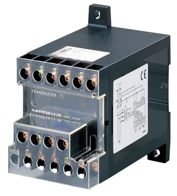
WATT TRANSDUCER
Functions & Features• Provides a DC output signal and a pulse totalizer signal in proportion to AC active power
• Convenient pulse unit output (Wh×10
n)
• Measuring bidirectional power flow
• DC output containing little ripple is ideal for computer input
• “Time division multiplication” method accepts distorted waveforms
• Isolation up to 2000 V AC
• High-density mounting
• Conforms to IEC 60688
Typical Applications• Centralized monitoring and control of power management system in a manufacturing facility or building
• SCR – Silicon Controlled Rectifier
MODEL: LTWT–[1][2][3][4][5]–[6][7]
ORDERING INFORMATION
• Code number: LTWT–[1][2][3][4][5]–[6][7]
Specify a code from below for each of [1] through [7].
(e.g. LTWT-115A2-R/T/Q)
• Special output range (For codes Z & 0)
• Specify the specification for option code /Q
(e.g. /C01)
• Use Ordering Information Sheet (No. ESU-3355).
How to determine Pulse Unit[Example]
3-phase / 3-wire, VT 3300/110 V, CT 250/5 A,
calibration range 750 W
10 [kWh/pulse] ÷ ((3300÷110) × (250÷5))
= 6.666 × 10
–3 [kWh/pulse]
= 6.666 [Wh/pulse]
Check that the required pulse unit is within the available frequency range, 0.006 – 3.12 Hz.
Input Range [W] ÷ (Calculated Pulse × 3600 [s])
= 750 ÷ (6.666 × 3600)
= 0.03125 [Hz]
[1] CONFIGURATION
1: 3-phase / 3-wire
2: Single-phase / 2-wire
3: Single-phase / 3-wire
4: 3-phase / 4-wire
[2] VT INPUT (unbalanced load)
For 3-phase / 4-wire, phase voltages (e.g. 110 V / √3 ) are used.
1: 100, 110, 115, 120 V AC
(Not selectable for single-phase / 3-wire system.)
2: 190, 200, 210, 220, 230, 240 V AC
(Not selectable for single-phase / 3-wire system.)
4: 380, 400, 415, 430, 440, 480 V AC
(Not selectable for single-phase / 3-wire system.)
A: 100 V / 200 V AC
(single-phase / 3-wire only)
[3] CT INPUT (unbalanced load)
Current
1: 1 A AC
2: 2 A AC
5: 5 A AC
[4] DC OUTPUT
Current
A: 4 – 20 mA DC (Load resistance 500 Ω max.)
D: 0 – 20 mA DC(Load resistance 500 Ω max.)
F: 0 – 10 mA DC (Load resistance 1000 Ω max.)
G: 0 – 1 mA DC (Load resistance 10 kΩ max.)
J: 0 – 5 mA DC (Load resistance 2000 Ω max.)
FW: -10 – +10 mA DC (Load resistance 1000 Ω max.)
GW: -1 – +1 mA DC (Load resistance 10 kΩ max.)
JW: -5 – +5 mA DC (Load resistance 2000 Ω max.)
Z: Specify current (See OUTPUT SPECIFICATIONS)
Voltage
1: 0 – 10 mV DC (Load resistance 10 kΩ min.)
2: 0 – 100 mV DC (Load resistance 100 kΩ min.)
3: 0 – 1 V DC (Load resistance 1000 Ω min.)
4: 0 – 10 V DC (Load resistance 10 kΩ min.)
5: 0 – 5 V DC (Load resistance 5000 Ω min.)
6: 1 – 5 V DC (Load resistance 5000 Ω min.)
1W: -10 – +10 mV DC (Load resistance 10 kΩ min.)
2W: -100 – +100 mV DC (Load resistance 100 kΩ min.)
3W: -1 – +1 V DC (Load resistance 1000 Ω min.)
4W: -10 – +10 V DC (Load resistance 10 kΩ min.)
5W: -5 – +5 V DC (Load resistance 5000 Ω min.)
0: Specify voltage (See OUTPUT SPECIFICATIONS)
[5] PULSE OUTPUT (open collector)
0: None
1: 2.777 Hz at 100 % input
2: Specify pulse unit (within 0.006 – 3.12 Hz)
[6] AUXILIARY POWER SUPPLY
AC Power
K3: 100 – 120V AC
(Operational voltage range 85 - 132 V, 47 - 66 Hz)
L3: 200 – 240V AC
(Operational voltage range 170 - 264 V, 47 - 66 Hz)
DC Power
R: 24 V DC
(Operational voltage range 24 V ±10 %, ripple 10 %p-p max.)
V: 48 V DC
(Operational voltage range 48 V ± 10 % , ripple 10 % p-p max.)
P: 110 V DC
(Operational voltage range 85 – 150 V, ripple 10 %p-p max.)
(CE not available)
[7] OPTIONS (multiple selections)
Terminal Cover
blank: Without
/T: With
Custom specification
(Refer to the custom specification list for difference
of specification and combination of code numbers.)
blank: none
/X1: Input range
/X2: Input span
Other Options
blank: none
/Q: Option other than the above (specify the specification)
SPECIFICATIONS OF OPTION: Q
COATING (For the detail, refer to M-System's web site.)
/C01: Silicone coating
/C02: Polyurethane coating
/C03: Rubber coating
GENERAL SPECIFICATIONS
Connection: M4 screw terminals (torque 1.2 N·m)
Screw terminal: Chrome-plated steel
Housing material: Flame-resistant resin (black)
Isolation: Voltage input to current input to DC output to pulse output to auxiliary power
Computation: Time division multiplication
Overrange output: Approx. -10 to +120 % at 1 – 5 V
Zero adjustment(DC output): -5 to + 5 % (front)
Span adjustment(DC output): 95 to + 105 % (front)
INPUT SPECIFICATIONS
Frequency: 50 or 60 Hz
•
Voltage inputOperational range: 0 – 120 % of rating
Overload capacity: 200 % of rating for 10 sec., 120 % continuous
• Current inputOperational range: 0 – 120 % of rating
Overload capacity: 4000 % of rating for 1 sec., 2000 % for 4 sec., 120 % continuous
■
How to determine Wattage Range Calibration Range [W] = Measuring Wattage ÷ ((VT Ratio) × (CT Ratio))
Check that the required calibration range is within the available range in the table. Specify this range when ordering.
[Example]
3-phase / 3-wire, measuring wattage 750 kW,
VT 3300/110 V, CT 250/5 A
750 × 10
3 [W] ÷ ((3300÷110) × (250÷5)) = 500 [W]
OUTPUT SPECIFICATIONS
■
DC Output• DC Current: -10 – +20 mA DC
Span: Min. 1 mA, max. 20 mA
Offset: Max. 1.5 times span
Load resistance: Output drive 10 V max.
• DC Voltage: -10 – +12 V DC
Minimum span: 5 mV
Offset: Max. 1.5 times span
Load resistance: Output drive 1 mA max. at ≥ 0.5 V
■
Pulse output: Open collector
0 Hz at 0 W (cutout at approx. 0.5 – 1.0 %)
Rating: 35 V DC @ 100 mA
ON voltage: ≤ 1 V at 100 mA
ON duration: Max. 0.5 sec., min. 50 msec. (approx.)
Frequency range: 0 – 2.777 Hz (0 – 100 %) standard; 0 – 0.006 Hz through 3.12 Hz is possible.
• 2.777 Hz at 100 % Input
[Example] 1000 W calibration range
2.777 [Hz] × 3600 [s] ÷ 1 [kW] = 10000 [pulses/kWh]
• Specified Pulse Unit:
Refers to how much electrical energy (kWh) consumption at the primary
of the VT and CT corresponds to the single output pulse per hour from
the transducer.
INSTALLATION
Power Consumption
•
AC: Approx. 2 VA
•
DC: Approx. 2 W (18 mA at 110 V)
Operating temperature: -10 to +55°C (14 to 131°F)
Operating humidity: 30 to 85 %RH (non-condensing)
Mounting: Surface or DIN rail
Weight: 450 g (0.99 lb)
PERFORMANCE in percentage of span
Accuracy: ±0.5 % (at 23°C ±10°C or 73.4°F ±18°F,
45 – 65 Hz)
Magnetic field (ext. origin) effect: ± 0.5 % (400 A/m)
Response time: ≤ 2 sec. (0 – 100 % ±1 %)
Ripple:
0.5 %p-p max.(The output ripple may increase when there is great
difference between the frequencies of input signal and power supply)
Line voltage effect:
±0.25 % over operational voltage range (Operational voltage range is
[K3: 90 to 132 V AC], [L3: 180 to 264 V AC] when the DC output code is
4W or the specified voltage is ≤ -9 V)
Insulation resistance: ≥ 100 MΩ with 500 V DC
Dielectric strength: 2000 V AC @ 1 minute
(voltage input to current input to DC output to pulse output to auxiliary power to ground)
Impulse withstand voltage: 1.2 / 50 μsec., ±5 kV
(input to output or ground)
STANDARDS & APPROVALS
EU conformity:
EMC Directive
EMI EN 61000-6-4
EMS EN 61000-6-2
Low Voltage Directive
EN 61010-1
Measurement Category II (input)
Installation Category II (auxiliary power)
Pollution Degree 2
Input to output or auxiliary power: Reinforced insulation (550 V)
Output to auxiliary power: Reinforced insulation (300 V)
RoHS Directive
EN 50581
CONNECTION DIAGRAM
EXTERNAL DIMENSIONS & TERMINAL ASSIGNMENTS unit: mm (inch)
M-System Việt Nam
Email: Sales@m-system.com.vn

")


 IT40SW5F/6F, IT50SW5F/6F, IT60SW5F/6F Series")


