
")
ALV DC ALARM


Tình trạng: In stock
Contact: 0989649965
ALV DC ALARM
Số lượt xem: 2064
Detail
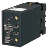
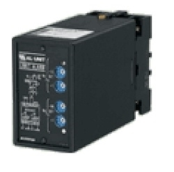
ALV Limit Alarms (rotary switch adj.) AL-UNIT
DC ALARM
Functions & Features
• Providing SPDT relay outputs at preset DC input levels
• Dual (Hi/Lo) trip
• Energized or de-energized coil at a tripped condition selectable
• Rotary switch setpoint adjustments
• Enclosed relays
• Relays can be powered 110 V DC
• Isolation up to 2000 V AC
• High-density mounting
Typical Applications
• Annunciator
• Various alarm applications
MODEL: ALV-[1][2][3]-[4][5]
ORDERING INFORMATION
• Code number: ALV-[1][2][3]-[4][5]
Specify a code from below for each [1] through [5].
(e.g. ALV-A13-B/Q)
• Special input range (For codes Z & 0)
• Specify the specification for option code /Q
(e.g. /C01/S01)
[1] INPUT
Current
A: 4 – 20 mA DC (Input resistance 250 Ω)
A1: 4 – 20 mA DC (Input resistance 50 Ω)
B: 2 – 10 mA DC (Input resistance 500 Ω)
C: 1 – 5 mA DC (Input resistance 1000 Ω)
D: 0 – 20 mA DC (Input resistance 50 Ω)
E: 0 – 16 mA DC (Input resistance 62.5 Ω)
F: 0 – 10 mA DC (Input resistance 100 Ω)
G: 0 – 1 mA DC (Input resistance 1000 Ω)
H: 10 – 50 mA DC (Input resistance 100 Ω)
J: 0 – 10 μA DC (Input resistance 1000 Ω)
K: 0 – 100 μA DC (Input resistance 1000 Ω)
GW: -1 – +1 mA DC (Input resistance 1000 Ω)
FW: -10 – +10 mA DC (Input resistance 100 Ω)
Z: Specify current (See INPUT SPECIFICATIONS)
Voltage
1: 0 – 10 mV DC (Input resistance 10 kΩ min.)
15: 0 – 50 mV DC (Input resistance 10 kΩ min.)
16: 0 – 60 mV DC (Input resistance 10 kΩ min.)
2: 0 – 100 mV DC (Input resistance 100 kΩ min.)
3: 0 – 1 V DC (Input resistance 1 MΩ min.)
4: 0 – 10 V DC (Input resistance 1 MΩ min.)
5: 0 – 5 V DC (Input resistance 1 MΩ min.)
6: 1 – 5 V DC (Input resistance 1 MΩ min.)
4W: -10 – +10 V DC (Input resistance 1 MΩ min.)
5W: -5 – +5 V DC (Input resistance 1 MΩ min.)
0: Specify voltage (See INPUT SPECIFICATIONS)
[2] SETPOINT 1 OUTPUT
1: Hi (coil energized at alarm)
2: Hi (coil de-energized at alarm)
3: Lo (coil energized at alarm)
4: Lo (coil de-energized at alarm)
[3] SETPOINT 2 OUTPUT
1: Hi (coil energized at alarm)
2: Hi (coil de-energized at alarm)
3: Lo (coil energized at alarm)
4: Lo (coil de-energized at alarm)
[4] POWER INPUT
AC Power
B: 100 V AC
C: 110 V AC
D: 115 V AC
F: 120 V AC
G: 200 V AC
H: 220 V AC
J: 240 V AC
DC Power
S: 12 V DC
R: 24 V DC
V: 48 V DC
P: 110 V DC
[5] OPTIONS
blank: none
/Q: With options (specify the specification)
SPECIFICATIONS OF OPTION: Q (multiple selections)
COATING (For the detail, refer to M-System's web site.)
/C01: Silicone coating
/C02: Polyurethane coating
/C03: Rubber coating
TERMINAL SCREW MATERIAL
/S01: Stainless steel
GENERAL SPECIFICATIONS
Construction: Plug-in
Connection: M3.5 screw terminals
Screw terminal: Chromated steel (standard) or stainless steel
Housing material: Flame-resistant resin (black)
Isolation: Input to output 1 to output 2 to power
Setpoint adjustments: 10-position rotary switches (front); 0 – 99 % independently; 1 % increments
Hysteresis (deadband): 0.7 – 2.5 %
Front LEDs: Red lights turn on when the coils are energized.
Power ON timer: Relays de-energized for approx. 2 seconds after power is turned on.
INPUT SPECIFICATIONS
■ DC Current:
Shunt resistor attached to the input terminals (0.5 W)
Specify input resistance value for code Z.
■ DC Voltage: -300 – +300 V DC
Minimum span: 10 mV
Offset: Max. 1.5 times span
Input resistance
Span 10 – 100 mV : ≥ 10 kΩ
Span 0.1 – 1 V : ≥ 100 kΩ
Span ≥ 1 V : ≥ 1 MΩ
OUTPUT SPECIFICATIONS
■ Relay Contact: 100 V AC @ 1 A (cos ø = 1)
120 V AC @ 1 A (cos ø = 1)
240 V AC @ 0.5 A (cos ø = 1)
30 V DC @ 1 A (resistive load)
Maximum switching voltage: 380 V AC or 125 V DC
Maximum switching power: 120 VA or 30 W
Minimum load: 5 V DC @ 10 mA
Mechanical life: 5 x 10⁷ cycles
For maximum relay life with inductive loads, external protection is recommended.
INSTALLATION
Power input
• AC: Operational voltage range: rating ±10 %,
50/60 ±2 Hz, approx. 2 VA
• DC: Operational voltage range: rating ±10 %, or 85 – 150 V for 110 V rating (ripple 10 % p-p max.)
approx. 2 W (80 mA at 24 V)
Operating temperature: -5 to +60°C (23 to 140°F)
Operating humidity: 30 to 90 %RH (non-condensing)
Mounting: Surface or DIN rail
Weight: 370 g (0.82 lb)
PERFORMANCE in percentage of span
Setpoint accuracy: ±0.5 %
Trip point repeatability: ±0.05 %
Temp. coefficient: ±0.015 %/°C (±0.008 %/°F)
Response time: Approx. 0.5 sec. (0 – 100 % at 90 % setpoint)
Line voltage effect: ±0.1 % over voltage range
Insulation resistance: ≥ 100 MΩ with 500 V DC
Dielectric strength: 2000 V AC @1 minute (input to output 1 to output 2 to power to ground)
EXTERNAL VIEW
DIMENSIONS unit: mm (inch)
TERMINAL ASSIGNMENTS unit: mm (inch)
SCHEMATIC CIRCUITRY & CONNECTION DIAGRAM
M-System Vietnam
Products
-
ARB RTD ALARM
-

ALR RTD ALARM
-

ALM POTENTIOMETER ALARM
-
ALDY TWO-WIRE TRANSMITTER ALARM
-

ALDN TWO-WIRE TRANSMITTER ALARM
Limit Alarms (rotary switch adj.) AL-UNIT
-

ALTG TACHOGENERATOR ALARM
Limit Alarms (rotary switch adj.) AL-UNIT
-

ALAC AC ALARM
Limit Alarms (rotary switch adj.) AL-UNIT
-

ALSP FREQUENCY ALARM (50 Hz minimum)
ALSP Limit Alarms (rotary switch adj.) AL-UNIT FREQUENCY ALARM (50 Hz minimum)
-

ALCT CT ALARM
ALCT Limit Alarms (rotary switch adj.) AL-UNIT CT ALARM
PRODUCTS LIST
- Signal Conditioners
- 2-wire Signal Conditioners
- Power Transducers
- Indicators
- Tower Lights
- Limit Alarms
- Gateway, Remote IO
- Paperless Recording System
- PC Recorder
- Web Data Loggers
- PID Control Components
- BA&Energy Monitoring Components
- Temperature Controllers
- Electric Actuators
- Lightning Surge Protectors
News Product
 IT40SW5F/6F, IT50SW5F/6F, IT60SW5F/6F Series")


STATISTIC
Visitor: 1050722Online: 19

