
")
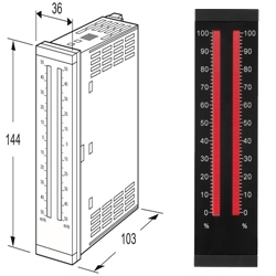
48NAV 48NAVA 48NAVD BARGRAPH INDICATING ALARM


Tình trạng: In stock
Contact: 0989649965
48NAV 48NAVA 48NAVD BARGRAPH INDICATING ALARM 36 x 144 mm Red, Amber, Green, Blue or Multicolor (red/orange/green) LED Vertical or horizontal mounting Dual or quad alarm 100-264 Vac or 24 Vdc powered IP 65 front panel cover
Số lượt xem: 1304
Products
-

48NDM BARGRAPH INDICATING ALARM
48NDM BARGRAPH INDICATING ALARM Potentiometer input
-

48NDR BARGRAPH INDICATING ALARM
48NDR BARGRAPH INDICATING ALARM RTD input
-
48NDT BARGRAPH INDICATING ALARM
48NDT BARGRAPH INDICATING ALARM Thermocouple input
-

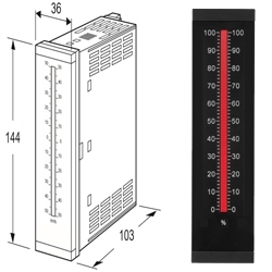
48NDV 48NDVA 48NDVD BARGRAPH INDICATING ALARM
48NDV 48NDVA 48NDVD BARGRAPH INDICATING ALARM 36 x 144 mm Red, Amber, Green, Blue or Multicolor (red/orange/green)LED Dual or quad alarm 100-264 Vac or 24 Vdc powered IP 65 front panel cover
-

48NAM BARGRAPH INDICATING ALARM
48NAM BARGRAPH INDICATING ALARM Potentiometer input
-

48NAR BARGRAPH INDICATING ALARM
48NAR BARGRAPH INDICATING ALARM 36 x 144 mm Red, Amber, Green, Blue or Multicolor (red/orange/green) LED Vertical or horizontal mounting Dual or quad alarm 100-264 Vac or 24 Vdc powered IP 65 front panel cover
-

48NAT BARGRAPH INDICATING ALARM
48NAT BARGRAPH INDICATING ALARM 36 x 144 mm Red, Amber, Green, Blue or Multicolor (red/orange/green) LED Vertical or horizontal mounting Dual or quad alarm 100-264 Vac or 24 Vdc powered IP 65 front panel cover
-
48SV2 BARGRAPH INDICATOR
48SV2 BARGRAPH INDICATOR 18 x 72 mm Red, Amber, Green, Blue LED Vertical or horizontal mounting 24 Vdc powered 51-segment LED (0 - 100% display: 51)
-

48NV BARGRAPH INDICATOR
48NV BARGRAPH INDICATOR 36 x 144 mm Red, Amber, Green, Blue LED Vertical or horizontal mounting 100-264 Vac or 24 Vdc powered IP 65 front panel cover
PRODUCTS LIST
- Signal Conditioners
- 2-wire Signal Conditioners
- Power Transducers
- Indicators
- Tower Lights
- Limit Alarms
- Gateway, Remote IO
- Paperless Recording System
- PC Recorder
- Web Data Loggers
- PID Control Components
- BA&Energy Monitoring Components
- Temperature Controllers
- Electric Actuators
- Lightning Surge Protectors
News Product
 IT40SW5F/6F, IT50SW5F/6F, IT60SW5F/6F Series")


STATISTIC
Visitor: 1061942Online: 15

