R3-TC2 TEMPERATURE CONTROL MODULE

Share on FacebookShare on Google+Tweet about this on TwitterShare on LinkedIn

Tình trạng: In stock

Contact: 0989649965

R3-TC2 TEMPERATURE CONTROL MODULE

Số lượt xem: 2271

Detail

R3-TC2

Remote I/O R3 Series

TEMPERATURE CONTROL MODULE

Functions & Features
• Two PID controllers
• Universal input x 2 points, control output x 4 points, discrete input x 2 points, clamp-on current sensor input x 2 points
• 2 universal inputs configurable to T/C, RTD, DC current or voltage independently
• Discrete inputs usable to switch PID bank or operation mode
• Control outputs configurable to MV, PV or alarm
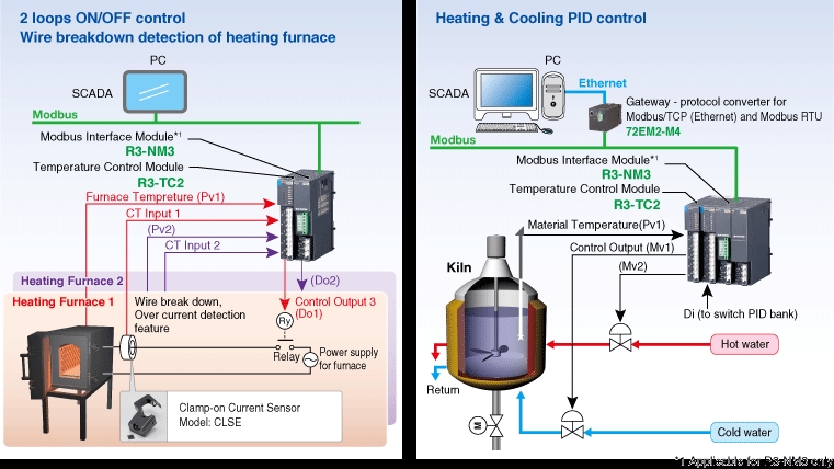
• Clamp-on current sensor input enables to detect heater wire break or over current
• Auto tuning function
• Minimum construction with an installation base (model: R3-BS02), interface module and temperature controller module
• Configurable with PC configurator (model: R3CON)
• Mixed installation with other I/O modules

MODEL: R3-TC2[1]S[2]

ORDERING INFORMATION
• Code number: R3-TC2[1]S[2]
Specify a code from below for each [1] and [2].
 (e.g. R3-TC2AS/Q)
• Specify the specification for option code /Q
 (e.g. /C01)

CONTROL LOOP
2: 2 loops

[1] CONTROL OUTPUT
A: 0 – 20 mA DC (Load resistance 500 Ω max.)
Open-collector 2 points
V: 0 – 10 V DC (Load resistance 2 kΩ max.)
Open-collector 2 points
P: 12 V pulse (Load resistance 600 Ω max.)
Open-collector 2 points

COMMUNICATION MODE
S: Single

[2] OPTIONS
blank: none
/Q: With options (specify the specification)

SPECIFICATIONS OF OPTION: Q
COATING (For the detail, refer to M-System's web site.)
/C01: Silicone coating
/C02: Polyurethane coating
/C03: Rubber coating

RELATED PRODUCTS
• Modbus Interface Module (model: R3-NM3)
(Not compatible with other Network modules)
• PC configurator software (model: R3CON)
Downloadable at M-System’s web site.
A dedicated cable is required to connect the module to the PC.  Please refer to the internet software download site or the users manual for the PC configurator for applicable cable types.
• Clamp-on current sensor (model: CLSE)
(Used for detecting the heater wire break)

GENERAL SPECIFICATIONS
Connection
 Internal bus
: Via the Installation Base (model: R3-BSx)
 Input, control output: M3 separable screw terminal (torque 0.5 N·m)
 Internal power: Via the Installation Base (model: R3-BSx)
Screw terminal: Nickel-plated steel
Isolation: Pv1 to Pv2 to CT1 or CT2 to Di1 or Di2 to MV1 or MV2 to Do1 or Do2 to internal bus or  internal power
CT Input waveform
  RMS sensing: Up to 15 % of 3rd harmonic content
RUN indicator: Bi-color (red/green) LED;
Red when the internal bus operates normally.
ERR indicator: Bi-color (red/green) LED; Red at device error;
Green in normal operating conditions.
Loop status indicator (RUN1): Red LED; turns on when loop 1 operating
Loop status indicator (AUTO1): Red LED; turns on during auto mode, turns off during manual mode at loop 1
Loop status indicator (ERR1): Red LED; turns on during error at loop 1
Loop status indicator (ALM1): Red LED; turns on when alarm trip on loop 1
Loop status indicator (RUN2): Red LED; turns on when loop 2 operating
Loop status indicator (AUTO2): Red LED; turns on during auto mode, turns off during manual mode at loop 2
Loop status indicator (ERR2): Red LED; turns on during error at loop 2
Loop status indicator (ALM2): Red LED; turns on when alarm trip on loop 2
Control mode: Standard PID, heating and cooling control (ON/OFF, PID)
Proportional band (P): 0.1 to 999.9 (temperature unit)
Integral time (I): 0.0 to 9999.9 sec.
Derivative time (D): 0.0 to 9999.9 sec.
Auto-tuning: Limit cycle method
Alarm: Deviation high & low, absolute high & low, etc.
Sampling cycle: 100 msec.
Control cycle: 0.1 to 99.9 sec.
MV output range: -5 - +105 %
Parameters: Stored in E2PROM; write/erase cycle endurance: less than 100 000
Parameter setting: With PC configurator software (model: R3CON)
User-configurable items: With PC configurator software (model: R3CON)
· Input type
· Input range
· Output range
· Cold junction compensation; CJC sensor attached to input terminal. CJC can be enabled or disabled per each universal input.

INPUT SPECIFICATIONS
Universal input 1, 2 (Pv1, Pv2)
For type and range configuration, refer to the instruction manual.
・DC Current:
Input range: 0 - 20 mA DC
Input resistance: 49.9 Ω resistor incorporated
DC voltage input
Input resistance:
≥ 10 kΩ (-1000 to +1000 mV DC)
Input resistance: ≥ 1 MΩ (-10 to + 10 V DC)
• Thermocouple
Input resistance: ≥ 10 kΩ
Input range: Refer to the table 1
Burnout sensing: ≤ 4 μA
Conformance range: Refer to the table 1
• RTD (2-wire or 3-wire)
Excitation: ≤ 0.33 mA
Allowable leadwire resistance: 20 Ω per wire
• Resistance
Excitation: ≤ 0.33 mA
Allowable leadwire resistance: 20 Ω per wire
• Potentiometer
Excitation: ≤ 0.33 mA
Allowable leadwire resistance: 20 Ω per wire
■ Clamp-on current sensor (CT1, CT2)
(Sensor model No.: AC input)
  CLSE-R5: 0 – 5 A
  CLSE-05: 0 – 50 A
  CLSE-10: 0 – 100 A
  CLSE-20: 0 – 200 A
  CLSE-40: 0 – 400 A
  CLSE-60: 0 – 600 A
Frequency: 50 / 60 Hz (45 - 65 Hz)
Operational range: 0 – 120 % of rating
Overload capacity:
  CLSE-R5: 10 A continuous
  CLSE-05: 60 A continuous
  CLSE-10: 120 A continuous
  CLSE-20: 240 A continuous
  CLSE-40: 480 A continuous
  CLSE-60: 720 A continuous
Be sure that the input voltage is of 480 V or less.
Discrete Input (Di1, Di2)
Contact rating: 3.3 V @1 mA
Detection levels:
≤ 15 kΩ / 0.5 V at close
≥ 350 kΩ / 2.5 V at open

OUTPUT SPECIFICATIONS
Four control outputs are configurable to Mv, Ao or Do.
Control Output (Mv1, Mv2)
Specify the type of output with the code number.
 DC Current: 0 – 20 mA DC
Operational range: 0 – 23 mA DC
Load resistance: ≤ 500 Ω
DC Voltage: 0 – 10 V DC
Operational range: 0 - 11.5 V DC
Load resistance: ≥ 2 kΩ
Voltage Pulse
Maximum frequency
: 1 Hz
Minimum pulse width: 1 msec.
Hi level: 12 V ±15 %
Lo level: ≤ 0.5 V
Load resistance: 600 Ω min.
■ Control Output (Do1, Do2)
• Open collector
Maximum frequency
: 1 Hz
Minimum pulse width: 1 msec.
Output rating: 50 V DC 100 mA (resistive load)
Saturation voltage: 0.5 V DC

INSTALLATION
Operating temperature: -10 to +55°C (14 to 131°F)
Operating humidity: 30 to 90 %RH (non-condensing)
Atmosphere: No corrosive gas or heavy dust
Mounting: Installation Base (model: R3-BSx)
Weight: 200 g (0.44 lb)

PERFORMANCE
Accuracy
• Pv1 or Pv2
: Refer to "Input type, range & conversion accuracy" section.
• CT1 or CT2: ±2 % (sensor error margin not included)
• MV1 or MV2: ±0.5 % (added to the input accuracy)
Data allocation: 8
Current consumption: ≤ 120 mA
Cold junction compensation error:
±2.0°C at 0 – 50°C (±3.6°F at 32 – 122°F)
Temp. coefficient
• Pv1 or
Pv2: ±0.03 %/°C (± 0.02 %/°F)
CT1 or CT2: ±0.03 %/°C (± 0.02 %/°F)
Response time
CT1 or CT2: ≤ 2 sec. (0 – 90 %)
Mv1 or Mv2: ≤ 1 sec. (0 – 90 %, DC output)
Burnout response: ≤ 10 sec.
Insulation resistance: ≥ 100 MΩ with 500 V DC
Dielectric strength: 1000 V AC @1 minute (Pv1 to Pv2 to CT1 or CT2 to Di1 or Di2 to MV1 or MV2 to Do1 or Do2 to internal bus or internal power)
1500 V AC @1 minute (internal power to FG)

INPUT TYPE, RANGE & CONVERSION ACCURACY

EXTERNAL VIEW

EXTERNAL DIMENSIONS & TERMINAL ASSIGNMENTS unit: mm (inch)

SCHEMATIC CIRCUITRY & CONNECTION DIAGRAM

SYSTEM CONFIGURATION EXAMPLES

M-System Vietnam
Email: sales@m-system.com.vn

PRODUCTS LIST

News Product

WL40VN Series - 920 MHz Band Wireless I/O (for use in Vietnam)
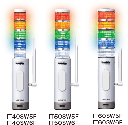
Wireless Tower Light (FCC Part 15 compliant wireless module) IT40SW5F/6F, IT50SW5F/6F, IT60SW5F/6F Series
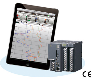
TR30-G Tablet Recorder  Web-enabled DAQ System
News

STATISTIC

Visitor: 1045282
Online: 3
0989649965
Sales@m-system.com.vnFacebook: M-System.com.vnZalo: 0989649965