M2XPA3
FREQUENCY TRANSMITTER
(PC programmable)
Functions & Features• Converts the output from a pulse-type transducer into a standard process signal
• PC programmable
• Sensor excitation
• Direct RS-422 input
Typical Applications• Positive displacement flowmeters, turbine flowmeters and vortex flowmeters
• Measuring rotation speed of a machine generating dry contact signals
MODEL: M2XPA3-[1][2][3]-[4][5]
ORDERING INFORMATION
• Code number: M2XPA3-[1][2][3]-[4][5]
Specify a code from below for each [1] through [5].
(e.g. M2XPA3-A14Z1-R/CE/Q)
• Input frequency (e.g. 0 – 10 kHz)
• Output (e.g. 0 - 10 mA)
• Specify the specification for option code /Q
(e.g. /C01/S01)
•
Non-specified orders will be shipped at the default factory settings as
shown in below. However, a power suffix code must be specified.
If
you specify a full code number without specific calibration ranges, the
input and output ranges are factory set to the default range.
Use Ordering Information Sheet (No. ESU-5104).
[Factory default setting]
PARAMETER: DEFAULTInput type: Open collector
Input amplitude: ----
Pulse sensing: DC coupled
Noise filter: None
Detecting level: 2 V
Frequency range: 0 – 200 kHz
Input zero frequency: 0 Hz
Input span frequency: 100 kHz
Linearization: No linearization
Low-end cutout: 0 % (No cutout)
Moving averaging samples: 1
Sensor excitation: 12 V DC / 20 mA
Output type: DC current
Output 0%: 4mA
Output 100%: 20mA
[1] INPUT
A1: Open collector
A2: Mechanical contact
B: Voltage pulse
G: Two-wire current pulse
J: RS-422 line driver pulse
Configurator
software is used to change the frequency range. The input type can be
switched to other than the one of the selected suffix code by selecting
the input type selectors inside the unit before software adjustment.
[2] EXCITATION
2: 4 V DC / 20 mA
3: 8 V DC / 20 mA
4: 12 V DC / 20 mA
Configurator software is used to change the excitation value.
[3] OUTPUT
Current
Z1: Range 0 – 20 mA DC
Voltage
V1: Range -2.5 – +2.5 V DC
V2: Range -10 – +10 V DC
(Configurator
software is used to adjust the output range and to change the output
over the described range of the selected suffix code.)
[4] POWER INPUT
AC Power
M2: 100 – 240 V AC (Operational voltage range 85 – 264 V,
47 – 66 Hz)
(90 – 264 V for UL)
DC Power
R: 24 V DC
(Operational voltage range 24 V ±10 %, ripple 10 %p-p max.)
P: 110 V DC
(Operational voltage range 85 – 150 V, ripple 10 %p-p max.)
(110 V ±10 % for UL)
[5] OPTIONS (multiple selections)
Standards & Approvals (must be specified)
/N: Without CE or UL
/CE: CE marking
/UL: UL approval, CE marking
Other Options
blank: none
/Q: Option other than the above (specify the specification)
SPECIFICATIONS OF OPTION: Q (multiple selections)
COATING (For the detail, refer to M-System's web site.)
/C01: Silicone coating
/C02: Polyurethane coating
/C03: Rubber coating (UL not available)
TERMINAL SCREW MATERIAL
/S01: Stainless steel (UL not available)
RELATED PRODUCTS
• PC configurator software (model: JXCON)
Downloadable at M-System’s web site.
A
dedicated cable is required to connect the module to the PC. Please
refer to the internet software download site or the users manual for the
PC configurator for applicable cable types.
GENERAL SPECIFICATIONS
Construction: Plug-in
Connection: M3 screw terminals (torque 0.8 N·m)
Screw terminal: Chromated steel (standard) or stainless steel
Housing material: Flame-resistant resin (black)
Isolation: Input to output to power
Overrange output: Approx. -15 to +115 % at 1 – 5 V
Zero adjustment: -5 to +5 % (front)
Span adjustment: 95 to 105 % (front)
Configuration: Via PC Configurator Software (model: JXCON) on the Windows PC connected to the front jack.
Programmable features include:
· I/O type and range
· Detecting level
· Sensor excitation
· Zero and span adjustments
· Low-end cutout
· Linearization
· Sample number for the moving average
DIP switch settings:
• Input Type
• Pulse Sensing (Capacitor coupled, DC coupled)
• Noise Filter (High, Low, None)
Status indicator LED: Blinking patterns indicate different operating status of the transmitter.
Excitation adjustment: 4 V, 8 V or 12 V DC
Configurator connection: 2.5 dia. miniature jack;
RS-232-C level
Low-end cutout: 0 – 115 % programmable;
No cutout with 0 % setting; hysteresis fixed at 1 % (factory set to: No cutout)
INPUT SPECIFICATIONS
Excitation: Shortcircuit protection; 30 mA max. at shortcircuit
Frequency ranges:
0 – 10 mHz, 0 – 100 mHz, 0 – 1 Hz, 0 – 10 Hz, 0 – 100 Hz,
0 – 1 kHz, 0 – 10 kHz, 0 – 200 kHz
(up to 10 Hz for mechanical contact)
If not specified, Input frequency factory default will be 0 – 100 kHz.
(0 – 10 Hz for mechanical contact)
Minimum pulse width time requirement: 2.5 μsec. for both ON and OFF. (50 msec. for mechanical contact)
Minimum span: 10 % of the selected frequency range
(5 % of the selected frequency range when the range is
0 – 200 kHz.)
Noise filter: See Table 2
Choose the noise filter type appropriate for the selected frequency range to ensure the described accuracy.
■
Open Collector & Mechanical Contact
Input requirements
EXC SENSING OFF ON
4V Approx. 3V/0.7mA ≥2kΩ/1V ≤200Ω/0.2V
8V Approx. 6V/1.5mA ≥4kΩ/3V ≤600Ω/1V
12V Approx. 9V/2.3mA ≥2kΩ/3V ≤400Ω/1V
Detecting level (detecting voltage in the internal circuit) factory default: 0.6 V (4 V excitation)
2 V (8 V / 12 V excitation)
■
Voltage Pulse
Waveform: Square or sine
Input impedance: ≥ 10 kΩ
Input amplitude: Min. 0.1 Vp-p, max. 100 Vp-p
Max. voltage between input terminals: See table 1.
Detecting level (detecting voltage in the internal circuit):
-2 – +4 V
■
Two-wire Current Pulse
Input resistance: Receiving resistor 100 Ω
Input range: 0 – 25 mA
Input amplitude: Min. 10 mAp-p, max. 25 mAp-p
Detecting level (detecting voltage in the internal circuit):
-2 – +4 V
■
RS-422 Line Driver Pulse
Receiver: Conforms to RS-422
OUTPUT SPECIFICATIONS
■ DC CurrentOutput range: 0 – 20 mA DC
Conformance range: 0 – 24 mA DC
Minimum span: 1 mA
Offset: Lower range can be any specific value within the output range provided that the minimum span is maintained.
Load resistance: Output drive 12 V max.
(e.g. 4 – 20 mA: 600 Ω [12 V ÷ 20 mA])
If not specified, the output range is 4 – 20 mA DC.
■
DC Voltage
Code V1 (narrow spans)
Conformance range: -3 – +3 V DC
Output range: -2.5 – +2.5 V DC
Minimum span: 250 mV
Code V2 (wide spans)Conformance range: -11.5 – +11.5 V DC
Output range: -10 – +10 V DC
Minimum span: 1 V
Offset: Lower range can be any specific value within the output range provided that the minimum span is maintained.
Load resistance: Output drive 1 mA max.
(e.g. 1 – 5 V: 5000 Ω [5 V ÷ 1 mA])
If not specified, the output range is shown below.
V1: 0 – 1 V DC
V2: 1 – 5 V DC
INSTALLATION
Power Consumption
•
AC:
Approx. 4 VA at 100 V
Approx. 5 VA at 200 V
Approx. 6 VA at 264 V
•
DC: Approx. 2 W
Operating temperature: -5 to +55°C (23 to 131°F)
Operating humidity: 30 to 90 %RH (non-condensing)
Mounting: Surface or DIN rail
Weight: 150 g (0.33 lb)
PERFORMANCE
Accuracy: Input accuracy + output accuracy
Inversely proportional to the span.
Input accuracy: ±0.03 % of the selected freq. range
(The
input span 100 kHz is used for calculation with 0 – 200 kHz range. The
input accuracy is fixed at ±0.03 % when [Frequency range ÷ Input span]
equals 1 or less.)
Output accuracy: ±0.03 % of the selected output range
See CALCULATION EXAMPLES OF OVERALL ACCURACY.
Temp. coefficient: ±0.015 %/°C (±0.008 %/°F) of I/O range at -5 to +55°C [23 to 131°F]
Response time: 0.5 sec. + 1 pulse cycle (0 – 90 %)
Line voltage effect: ±0.1 % over voltage range
Insulation resistance: ≥ 100 MΩ with 500 V DC
Dielectric strength: 2000 V AC @1 minute (input to output to power to ground)
CALCULATION EXAMPLES OF OVERALL ACCURACY
[Example] Open collector input, 0 – 50 kHz; 1 – 5 V output.
Selected freq. range (100 kHz) ÷ Input span (50 kHz)× Accuracy (0.03 %)= 0.06 % (Input accuracy)
Selected output range (20 V) ÷ Output span (4 V) × Accuracy (0.03 %)= 0.15 % (Output accuracy)
Overall accuracy = 0.06 + 0.15 = ±0.21 %
STANDARDS & APPROVALS
EU conformity:
EMC Directive
EMI EN 61000-6-4
EMS EN 61000-6-2
Low Voltage Directive
EN 61010-1
Installation Category II
Pollution Degree 2
Input or output to power: Reinforced insulation (300 V)
Input to output: Basic insulation (300 V)
RoHS Directive
EN 50581
Approval:
UL/C-UL nonincendive Class I, Division 2,
Groups A, B, C, and D
(ANSI/ISA-12.12.01, CAN/CSA-C22.2 No.213)
UL/C-UL general safety requirements
(UL 61010-1, CAN/CSA-C22.2 No.61010-1)
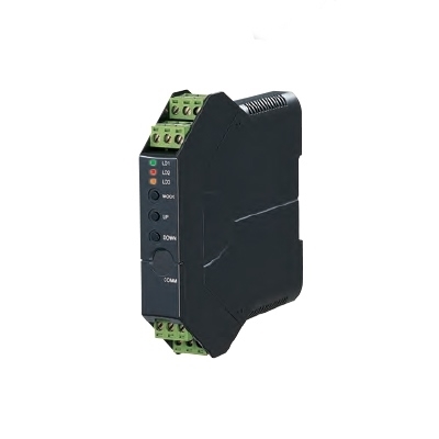
EXTERNAL VIEW
Refer to the instruction manual for detailed procedures.
EXTERNAL DIMENSIONS & TERMINAL ASSIGNMENTS unit: mm (inch)
SCHEMATIC CIRCUITRY & CONNECTION DIAGRAM
EXPLANATIONS OF TERMS
Low-end cutout:
The function where the output signal is forced to 0% below the setpoint input. Hysteresis is fixed at 1%.
[Example] Input zero frequency 0 Hz
Input span frequency 1 kHz
Low-end cutout 10 %
M-System Việt Nam
Email: Sales@m-system.com.vn

")


 IT40SW5F/6F, IT50SW5F/6F, IT60SW5F/6F Series")


