
")
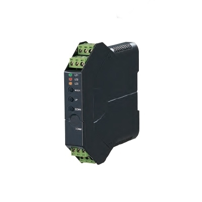
JRP2 ENCODER SPEED TRANSMITTER


Tình trạng: In stock
Contact: 0989649965
JRP2 ENCODER SPEED TRANSMITTER Converts a two-phase forward and reverse rotation pulse signal with 90 degree phase difference into a forward and reverse speed signal. Open collector, voltage pulse or RS-422 line driver pulse inputs Excitation 5 V, 12 V or 24 V 85-132 Vac or 12, 24, 48, 110 Vdc powered Applications: Measuring moving speed of a machine with a rotary encoder
JRP2 ENCODER SPEED TRANSMITTER
Số lượt xem: 1180
Detail
Products
-
M5PA FREQUENCY TRANSMITTER
M5PA FREQUENCY TRANSMITTER Open collector, mechanical contact, 5V/12V/24V pulse. Specific input range up to 100 kHz 100-240 Vac or 24 Vdc powered (CE for 24 Vdc type)
-

M2PP PULSE ISOLATOR
M2PP PULSE ISOLATOR Mechanical contact, open collector or voltage pulse input; 0-10 kHz max. Open collector, voltage pulse or mercury relay output 100-240 Vac or 24 Vdc powered UL Class I, Div. 2 approval
-
M2XPA3 FREQUENCY TRANSMITTER
M2XPA3 FREQUENCY TRANSMITTER Open collector, mechanical contact, voltage pulse, two-wire current, RS-422 line driver selectable; 0-200 kHz max. Excitation 4 V, 8 V or 12 V selectable Output selectable within 0-20 mA and ±10 V 100-240 Vac or 24 Vdc powered UL/cUL Class I, Div. 2 approval
-

M2SP LOW FREQUENCY TRANSMITTER
M2SP LOW FREQUENCY TRANSMITTER Dry contact or voltage pulse. Specific input range up to 10 kHz Excitation 12 V @30 mA 100-240 Vac or 24 Vdc powered UL/cUL Class I, Div. 2 approval
-

W2SP LOW FREQUENCY TRANSMITTER
W2SP LOW FREQUENCY TRANSMITTER Dry contact or voltage pulse. Specific input range up to 10 kHz Excitation 12 V @30 mA Independent current/voltage output ranges can be specified. 100-240 Vac or 24 Vdc powered UL/cUL Class I, Div. 2 approval
-
M6SPA M6XPA M6DPA FREQUENCY TRANSMITTER
M6SPA M6XPA M6DPA FREQUENCY TRANSMITTER Open collector, mechanical contact, 5V/24V pulse. Specific input range up to 100 kHz 24 Vdc powered
-
W5PA FREQUENCY TRANSMITTER
W5PA FREQUENCY TRANSMITTER Open collector, mechanical contact, 5V/12V/24V pulse. Specific input range up to 100 kHz Independent output ranges selectable 100-240 Vac or 24 Vdc powered (CE for 24 Vdc type)
-
M3LPA2 FREQUENCY TRANSMITTER
M3LPA2 FREQUENCY TRANSMITTER Open collector, dry contact, voltage pulse, two-wire current, RS-422 line driver selectable; 0-200 kHz max. Excitation 4 V, 8 V or 12 V selectable Output selectable within 0-20 mA and ±10 V 100-240 Vac or 24 Vdc powered DIP switch or PC configuration 101-point linearization using the PC Configurator
-

W2AP DC/FREQUENCY CONVERTER
W2AP DC/FREQUENCY CONVERTER Specific input range up to 300 V Open collector, 5V pulse or mercury relay output. Specific output range up to 10 kHz. 100-240 Vac or 24 Vdc powered. UL/cUL Class I, Div. 2 approval
PRODUCTS LIST
- Signal Conditioners
- 2-wire Signal Conditioners
- Power Transducers
- Indicators
- Tower Lights
- Limit Alarms
- Gateway, Remote IO
- Paperless Recording System
- PC Recorder
- Web Data Loggers
- PID Control Components
- BA&Energy Monitoring Components
- Temperature Controllers
- Electric Actuators
- Lightning Surge Protectors
News Product
 IT40SW5F/6F, IT50SW5F/6F, IT60SW5F/6F Series")


STATISTIC
Visitor: 1045369Online: 5

