
")
47LPA Digital Panel Meters


Tình trạng: In stock
Contact: 0989649965
Digital Panel Meters 47 Series FREQUENCY INPUT DIGITAL PANEL METER
Số lượt xem: 1197
Detail
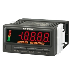
47LPA
Digital Panel Meters 47 Series
FREQUENCY INPUT DIGITAL PANEL METER
(4½ digit, LED display type)
Functions & Features
• 4 ½ digit digital panel meter
• 1/8 DIN size
• Accepts a pulse train input to measure rotation count or period
• Scaled reading representing speed (m/s), rotation (rpm) and other counts
• Alarm tone optional
• Max. and Min. value display
• IP66 front panel
• Separable terminal block
• Rear terminal cover for safety strapped to the meter
MODEL: 47LPA-1[1][2][3]-[4][5]
ORDERING INFORMATION
• Code number: 47LPA-1[1][2][3]-[4][5]
Specify a code from below for each of [1] through [5].
(e.g. 47LPA-1A1G-M2/B/Q)
• Specify the specification for option code /Q
(e.g. /C01/S01/SET)
INPUT
1: Open collector or voltage pulse
[1] DC OUTPUT
0: Without
Current
A: 4 – 20 mA DC (Load resistance 550 Ω max.)
D: 0 – 20 mA DC (Load resistance 550 Ω max.)
Voltage
4: 0 – 10 V DC (Load resistance 10 kΩ min.)
5: 0 – 5 V DC (Load resistance 5000 Ω min.)
6: 1 – 5 V DC (Load resistance 5000 Ω min.)
4W: -10 – +10 V DC (Load resistance 10 kΩ min.)
[2] ALARM OUTPUT
0: None
1: N.O. relay contact, 4 points
2: SPDT relay contact, 2 points
[3] DISPLAY COLOR
R: Red
YR: Orange
G: Green
BG: Bluegreen
B: Blue
W: White
[4] POWER INPUT
AC Power
M2: 100 – 240 V AC (Operational voltage range 85 – 264 V, 50/60 Hz)
DC Power
R: 24 V DC
(Operational voltage range 24 V ±10 %, ripple 10 %p-p max.)
P: 110 V DC
(Operational voltage range 85 – 150 V, ripple 10 %p-p max.)
[5] OPTIONS (multiple selections)
Alarm Tone
blank: Without
/B: With (selectable only with alarm output)
Other Options
blank: none
/Q: Option other than the above (specify the specification)
SPECIFICATIONS OF OPTION: Q (multiple selections)
COATING (For the detail, refer to M-System's web site.)
Moving parts and indicators are not coated.
/C01: Silicone coating
/C02: Polyurethane coating
/C03: Rubber coating
TERMINAL SCREW MATERIAL
/S01: Stainless steel
EX-FACTORY SETTING
/SET: Preset according to the Ordering Information Sheet
(No. ESU-9515)
GENERAL SPECIFICATIONS
Construction: Panel flush mounting
Degree of protection: IP66; applicable to the front of the panel meter mounted according to the specified panel cutout
Connection: M3 separable screw terminal (torque 0.6 N·m)
Screw terminal: Nickel-plated steel (standard) or stainless steel
Housing material: Flame-resistant resin (gray)
Isolation: Input to DC output to HH output or H output to
L output or LL output to power
Setting: (Front button)
• Scaled range
• Input type
• Alarm setpoint
• Hysteresis (deadband)
• Others
(Refer to the instruction manual for details)
Lockout setting: Prohibiting certain operations; protecting settings
DISPLAY
Display: 16 mm (.63) high, 4 ½ digits, 7-segment LED
Input indication: ‘D/P’ turns on for 1 second after a valid pulse train has been detected (applied to 1/100 scaled signal for the input ranges F10K, F0.1M).
‘Tch’ turns on with control input.
Display range: -19999 to 19999
Decimal point position: 10–1, 10–2, 10–3, 10–4 or none
Zero indication: Higher-digit zeros are suppressed.
Over-range indication: ‘-19999’ or ‘19999’ blinking for display values out of the scaled range.
‘S.ERR’ and ‘Max’ blinking when the input signal is out of the usable range.
Alarm status indication
LL indicator: Green LED turns on when the LL alarm is tripped.
L indicator: Green LED turns on when the L alarm is tripped.
H indicator: Red LED turns on when the H alarm is tripped.
HH indicator: Red LED turns on when the HH alarm is tripped.
P indicator: Amber LED turns on when none of the other alarms is tripped.
Only ‘P’ turns on with no-alarm-output type. ‘LL’ or ‘HH’ does not turn on with dual-alarm-output type.
All setpoints can be independently set either for Hi or Lo alarm trip.
Function indicators:
Zro, Spn, D/P, Tch, Fnc, Min, Max
Display mode status and operation status, amber ON or blink
Engineering unit indication: Sticker label attached
DC, AC, mV, V, kV, μA, mA, A, kA, mW, W,
kW, var, kvar, Mvar, VA, Hz, Ω, kΩ, MΩ,
cm, mm, m, m/sec, mm/min, cm/min, m/min,
m/h, m/s2, inch, ℓ, ℓ/s, ℓ/min, ℓ/h, m3, m3/sec,
m3/min, m3/h, Nm3/h, N·m, N/m2, g, kg, kg/h,
N, kN, Pa, kPa, MPa, t, t/h, ℃, °F, %RH, J,
kJ, MJ, rpm, sec, min, min-1, pH, %, ppm, etc.
INPUT SPECIFICATIONS
Sensor excitation: 12 V DC ±10 %, 30 mA
Current limit protection at approx. 60 mA
Frequency range: 0 – 0.01 Hz through 100 kHz
A wave that has constant frequency and variable duty ratio cannot be measured.
Time period range: 0 – 1 sec. through 100 sec.
Minimum pulse width requirements: 5 μsec. for both ON and OFF
Default setting: 0 – 100 kHz
■ Open Collector
Detecting voltage/current: Approx. 8 V DC @ 1.6 mA
Detecting levels: ≤ 300 Ω / 0.6 V for ON;
≥ 10 kΩ / 4.5 V for OFF
■ Voltage Pulse
Voltage range: 0 – 5 through 26.4 V
±5 – ±26.4 V (equal amplitude at both poles, or ±10 V min. with frequency ≥ 50 kHz)
Waveform: Square (detecting sinking pulse edges)
Input impedance: ≥ 10 kΩ
Low level: -26.4 – 0.6 V DC
High level: 4.5 – 26.4 V DC
■ Control Input: Halt measuring
Detecting time: ≥ 200 msec.
Detecting levels: 4.5 – 26.4 V or short circuit across the terminals 1 and 5 for ON; -26.4 – 0.6 V for OFF
OUTPUT SPECIFICATIONS
■ DC Output
• DC Current
Operational range: -5 – +105 %
• DC Voltage
Operational range: -5 – +105 %
■ Alarm Output: Relay contact
Rated load: 250 V AC @ 3 A (cos ø = 1)
30 V DC @ 3 A (resistive load)
Maximum switching voltage: 250 V AC, 30 V DC
Maximum switching power: 750 VA, 90 W (resistive load)
Minimum load: 5 V DC @ 10 mA
Mechanical life: ≥ 5 × 10⁶ cycles (rate 180 cycles/min.)
INSTALLATION
Power consumption
•AC: Approx. 6.5VA
•DC: Approx. 3 W
Operating temperature: -10 to +55°C (14 to 131°F)
Operating humidity: 30 to 90 %RH (non-condensing)
Mounting: Panel flush mounting
Weight: 300 g (0.66 lb)
PERFORMANCE
Accuracy
Display: ±0.1 % or ±1 digit
Output: ±0.1 % (DC output = display + output)
Temp. coefficient: ±0.015 %/°C (±0.008 %/°F)
Output resolution: Max. 14 bits
Response time: [One input cycle + 0.5 sec.] or less (alarm output: 0 – 100 % at 90 % setpoint)
[One input cycle + 0.5 sec.] or less
(DC output: 0 – 90 %)
Line voltage effect: ±0.1 % over voltage range
Insulation resistance: ≥ 100 MΩ with 500 V DC
Dielectric strength: 2000 V AC @ 1 minute (input to DC output to HH output or H output to L output or LL output to power to ground)
STANDARDS & APPROVALS
EU conformity:
EMC Directive
EMI EN 61000-6-4
EMS EN 61000-6-2
Low Voltage Directive
EN 61010-1
Measurement Category II (alarm output)
Installation Category II (power)
Pollution degree 2
Input or DC output to alarm output to power: Reinforced insulation
(300 V)
Input to DC output: Basic insulation (300 V)
RoHS Directive
EN 50581
Protection against access to the terminal blocks:
Finger protection (VDE 0660-514)
Products
-

43AL1 LOOP POWERED DIGITAL PANEL METER
43AL1 Digital Panel Meters 43 Series
-

43DV2 DC INPUT DIGITAL PANEL METER
43DV2 Digital Panel Meters 43 Series
-

40LV DC INPUT DIGITAL PANEL METER
40LV Digital Panel Meters 40 Series
-
40DV DC INPUT DIGITAL PANEL METER
40DV Digital Panel Meters 40 Series
-

40DT THERMOCOUPLE INPUT DIGITAL PANEL METER
40DT Digital Panel Meters 40 Series
-

40DR RTD INPUT DIGITAL PANEL METER
40DR Digital Panel Meters 40 Series
-

40DPT AC VOLTAGE INPUT DIGITAL PANEL METER
40DPT Digital Panel Meters 40 Series
-

40DN LOOP POWERED DIGITAL PANEL METER
40DN Digital Panel Meters 40 Series
-

40DCT AC CURRENT INPUT DIGITAL PANEL METER
40DCT Digital Panel Meters 40 Series
PRODUCTS LIST
- Signal Conditioners
- 2-wire Signal Conditioners
- Power Transducers
- Indicators
- Tower Lights
- Limit Alarms
- Gateway, Remote IO
- Paperless Recording System
- PC Recorder
- Web Data Loggers
- PID Control Components
- BA&Energy Monitoring Components
- Temperature Controllers
- Electric Actuators
- Lightning Surge Protectors
News Product
 IT40SW5F/6F, IT50SW5F/6F, IT60SW5F/6F Series")


STATISTIC
Visitor: 1045859Online: 7

